Example for Configuring Inter-AS BGP VPLS in Option B Mode (ASBRs Functioning as PEs)
The backbone network spans two ASs. ASBRs are connected through MP-EBGP and function as PEs.
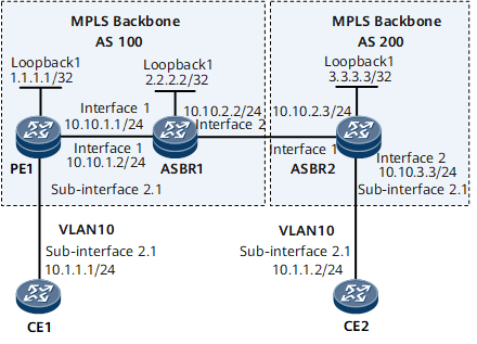
Networking Requirements
On the inter-AS BGP VPLS Option B network shown in Figure 1, ASBRs advertise routes and function as PEs to manage VPN routes. This reduces the number of PEs to be deployed and increases the performance requirements for ASBRs.

Configuration Roadmap
The configuration roadmap is as follows:
Establish an EBGP peer relationship between ASBRs, enable the L2VPN-AD address family, and trigger the establishment of a local IFNET tunnel. Configure a common BGP VPLS service and bind it to an AC interface.
Establish an MP-IBGP peer relationship between each PE and its ASBR in each same AS.
Data Preparation
To complete the configuration, you need the following data:
MPLS LSR IDs of PEs and ASBRs
RD, VPN target, and site ID of a VSI on each PE
- VPN-target filtering enabled on PEs and disabled on ASBRs
Procedure
- Configure IP addresses for interfaces.
# Configure CE1.
<HUAWEI> system-view
[~HUAWEI] sysname CE1
[*HUAWEI] commit
[~CE1] interface gigabitethernet 0/1/0
[*CE1-GigabitEthernet0/1/0] undo shutdown
[*CE1-GigabitEthernet0/1/0] quit
[*CE1] interface gigabitethernet 0/1/0.1
[*CE1-GigabitEthernet0/1/0.1] ip address 10.1.1.1 24
[*CE1-GigabitEthernet0/1/0.1] quit
[*CE1] commit
# Configure PE1.
<HUAWEI> system-view
[~HUAWEI] sysname PE1
[*HUAWEI] commit
[~PE1] interface loopback1
[*PE1-Loopback1] ip address 1.1.1.1 32
[*PE1-Loopback1] quit
[*PE1] interface gigabitethernet 0/1/0
[*PE1-GigabitEthernet0/1/0] undo shutdown
[*PE1-GigabitEthernet0/1/0] quit
[*PE1] interface gigabitethernet 0/1/0.1
[*PE1-GigabitEthernet0/1/0.1] quit
[*PE1] interface gigabitethernet 0/1/8
[*PE1-GigabitEthernet0/1/8] undo shutdown
[*PE1-GigabitEthernet0/1/8] ip address 10.10.1.1 24
[*PE1-GigabitEthernet0/1/8] quit
[*PE1] commit
# Configure ASBR1.
<HUAWEI> system-view
[~HUAWEI] sysname ASBR1
[*HUAWEI] commit
[~ASBR1] interface loopback1
[*ASBR1-Loopback1] ip address 2.2.2.2 32
[*ASBR1-Loopback1] quit
[*ASBR1] interface gigabitethernet 0/1/0
[*ASBR1-GigabitEthernet0/1/0] undo shutdown
[*ASBR1-GigabitEthernet0/1/0] ip address 10.10.2.2 24
[*ASBR1-GigabitEthernet0/1/0] quit
[*ASBR1] interface gigabitethernet 0/1/8
[*ASBR1-GigabitEthernet0/1/8] undo shutdown
[*ASBR1-GigabitEthernet0/1/8] ip address 10.10.1.2 24
[*ASBR1-GigabitEthernet0/1/8] quit
[*ASBR1] interface gigabitethernet 0/1/8.1
[*ASBR1-GigabitEthernet0/1/8.1] quit
[*ASBR1] commit
# Configure ASBR2.
<HUAWEI> system-view
[~HUAWEI] sysname ASBR2
[*HUAWEI] commit
[~ASBR2] interface loopback1
[*ASBR2-Loopback1] ip address 3.3.3.3 32
[*ASBR2-Loopback1] quit
[*ASBR2] interface gigabitethernet 0/1/0
[*ASBR2-GigabitEthernet0/1/0] undo shutdown
[*ASBR2-GigabitEthernet0/1/0] ip address 10.10.3.3 24
[*ASBR2-GigabitEthernet0/1/0]  quit
[*ASBR2] interface gigabitethernet 0/1/0.1
[*ASBR2-GigabitEthernet0/1/0.1] quit
[*ASBR2] interface gigabitethernet 0/1/8
[*ASBR2-GigabitEthernet0/1/8]  undo shutdown
[*ASBR2-GigabitEthernet0/1/8] ip address 10.10.2.3 24
[*ASBR2-GigabitEthernet0/1/8] quit
[*ASBR2] commit
# Configure CE2.
<HUAWEI> system-view
[~HUAWEI] sysname CE2
[~HUAWEI] commit
[~CE2] interface gigabitethernet 0/1/0
[*CE2-GigabitEthernet0/1/0] undo shutdown
[*CE2-GigabitEthernet0/1/0] quit
[*CE2] interface gigabitethernet 0/1/0.1
[*CE2-GigabitEthernet0/1/0.1] ip address 10.1.1.2 24
[*CE2-GigabitEthernet0/1/0.1] quit
[*CE2] commit
- Configure an IGP on the backbone network.
# Configure PE1.
[~PE1] ospf 1
[*PE1-ospf-1] bgp-ls enable
[*PE1-ospf-1] area 0.0.0.0
[*PE1-ospf-1-area-0.0.0.0] network 1.1.1.1 0.0.0.0
[*PE1-ospf-1-area-0.0.0.0] network 10.10.1.0 0.0.0.255
[*PE1-ospf-1-area-0.0.0.0] quit
[*PE1-ospf-1] quit
[*PE1] commit
# Configure ASBR1.
[~ASBR1] ospf 1
[*ASBR1-ospf-1] bgp-ls enable
[*ASBR1-ospf-1] area 0.0.0.0
[*ASBR1-ospf-1-area-0.0.0.0] network 2.2.2.2 0.0.0.0
[*ASBR1-ospf-1-area-0.0.0.0] network 10.10.1.0 0.0.0.255
[*ASBR1-ospf-1-area-0.0.0.0] network 10.10.2.0 0.0.0.255
[*ASBR1-ospf-1-area-0.0.0.0] quit
[*ASBR1-ospf-1] quit
[*ASBR1] commit
# Configure ASBR2.
[~ASBR2] ospf 1
[*ASBR2-ospf-1] bgp-ls enable
[*ASBR2-ospf-1] area 0.0.0.0
[*ASBR2-ospf-1-area-0.0.0.0] network 3.3.3.3 0.0.0.0
[*ASBR2-ospf-1-area-0.0.0.0] network 10.10.2.0 0.0.0.255
[*ASBR2-ospf-1-area-0.0.0.0] network 10.10.3.0 0.0.0.255
[*ASBR2-ospf-1-area-0.0.0.0] quit
[*ASBR2-ospf-1] quit
[*ASBR2] commit
- Configure basic MPLS functions and establish LSPs.
# Configure PE1.
[~PE1] mpls lsr-id 1.1.1.1
[*PE1] mpls
[*PE1-mpls] quit
[*PE1] mpls ldp
[*PE1-mpls-ldp] quit
[*PE1] commit
# Configure ASBR1.
[~ASBR1] mpls lsr-id 2.2.2.2
[*ASBR1] mpls
[*ASBR1-mpls] quit
[*ASBR1] mpls ldp
[*ASBR1-mpls-ldp] quit
[*ASBR1] interface gigabitethernet 0/1/8
[*ASBR1-GigabitEthernet0/1/8] mpls
[*ASBR1-GigabitEthernet0/1/8] mpls ldp
[*ASBR1-GigabitEthernet0/1/8] quit
[*ASBR1] commit
# Configure ASBR2.
[~ASBR2] mpls lsr-id 3.3.3.3
[*ASBR2] mpls
[*ASBR2-mpls] quit
[*ASBR2] mpls ldp
[*ASBR2-mpls-ldp] quit
[*ASBR2] interface gigabitethernet 0/1/8
[*ASBR2-GigabitEthernet0/1/8] mpls
[*ASBR2-GigabitEthernet0/1/8] quit
[*ASBR2] interface gigabitethernet 0/1/0
[*ASBR2-GigabitEthernet0/1/0] mpls
[*ASBR2-GigabitEthernet0/1/0] quit
[*ASBR2] commit
- Configure an MP-IBGP peer relationship within each AS.
# Configure PE1.
[~PE1] bgp 100
[*PE1-bgp] peer 2.2.2.2 as-number 100
[*PE1-bgp] peer 2.2.2.2 connect-interface loopback 1
[*PE1-bgp] l2vpn-ad-family
[*PE1-bgp-af-l2vpn-ad] policy vpn-target
[*PE1-bgp-af-l2vpn-ad] tunnel-selector s1
[*PE1-bgp-af-l2vpn-ad] signaling vpls
[*PE1-bgp-af-l2vpn-ad] peer 2.2.2.2 enable
Warning: This operation will reset the peer session. Continue? [Y/N]:y
[*PE1-bgp-af-l2vpn-ad] quit
[*PE1-bgp] quit
[*PE1] commit
# Configure ASBR1.
[~ASBR1] bgp 100
[*ASBR1-bgp] peer 1.1.1.1 as-number 100
[*ASBR1-bgp] peer 1.1.1.1 connect-interface loopback 1
[*ASBR1-bgp] peer 10.10.2.3 as-number 200
[*ASBR1-bgp] peer 10.10.2.3 connect-interface gigabitethernet 0/1/0
[*ASBR1-bgp] l2vpn-ad-family
[*ASBR1-bgp-af-l2vpn-ad] undo policy vpn-target
[*ASBR1-bgp-af-l2vpn-ad] tunnel-selector s1
[*ASBR1-bgp-af-l2vpn-ad] signaling vpls
[*ASBR1-bgp-af-l2vpn-ad] peer 1.1.1.1 enable
Warning: This operation will reset the peer session. Continue? [Y/N]:y
[*ASBR1-bgp-af-l2vpn-ad] peer 10.10.2.3 enable
Warning: This operation will reset the peer session. Continue? [Y/N]:y
[*ASBR1-bgp-af-l2vpn-ad] quit
[*ASBR1-bgp] quit
[*ASBR1] commit
# Configure ASBR2.
[~ASBR2] bgp 200
[*ASBR2-bgp] peer 10.10.2.2 as-number 200
[*ASBR2-bgp] peer 10.10.2.2 connect-interface gigabitethernet 0/1/0
[*ASBR2-bgp] l2vpn-ad-family
[*ASBR2-bgp-af-l2vpn-ad] undo policy vpn-target
[*ASBR2-bgp-af-l2vpn-ad] tunnel-selector s1
[*ASBR2-bgp-af-l2vpn-ad] signaling vpls
[*ASBR2-bgp-af-l2vpn-ad] peer 10.10.2.2 enable
Warning: This operation will reset the peer session. Continue? [Y/N]:y
[*ASBR2-bgp-af-l2vpn-ad] quit
[*ASBR2-bgp] quit
[*ASBR2] commit
After completing the configurations, run the display bgp l2vpn-ad peer command on each PE or ASBR. The command output shows that the MP-IBGP peer relationship status is Established.
The following example uses the command output on PE1.
[~PE1] display bgp l2vpn-ad peer BGP local router ID : 3.3.3.3 Local AS number : 200 Total number of peers : 2 Peers in established state : 2 Peer V AS MsgRcvd MsgSent OutQ Up/Down State PrefRcv 4.4.4.4 4 200 8 8 0 00:02:32 Established 1 10.10.2.2 4 100 189 187 0 02:39:53 Established 1 - Configure BGP VPLS.
# Configure PE1.
[~PE1] mpls l2vpn
[*PE1-l2vpn] quit
[*PE1-tunnel-policy-p1] tunnel-policy p1
[*PE1-tunnel-policy-p1] tunnel select-seq bgp ldp load-balance-number 1
[*PE1-tunnel-policy-p1] tunnel-selector s1 permit node 10
[*PE1-tunnel-selector] apply tunnel-policy p1
[*PE1-tunnel-selector] quit
[*PE1] vsi v1
[*PE1-vsi-v1] pwsignal bgp
[*PE1-vsi-v1-bgp] route-distinguisher 10.10.1.1:1
[*PE1-vsi-v1-bgp] vpn-target 100:1 import-extcommunity
[*PE1-vsi-v1-bgp] vpn-target 100:1 export-extcommunity
[*PE1-vsi-v1-bgp] site 1 range 10 default-offset 0
[*PE1-vsi-v1-bgp] mpls ldp
[*PE1-mpls-ldp] ipv4-family
[*PE1-mpls-ldp-ipv4] quit
[*PE1-mpls-ldp] quit
[*PE1] interface gigabitethernet0/1/0.1
[*PE1-GigabitEthernet0/1/0.1] shutdown
[*PE1-GigabitEthernet0/1/0.1] vlan-type dot1q 10
[*PE1-GigabitEthernet0/1/0.1] l2 binding vsi v1
[*PE1-GigabitEthernet0/1/0.1] undo shutdown
[*PE1-GigabitEthernet0/1/0.1] quit
[*PE1] commit
# Configure ASBR1.
[~ASBR1] mpls l2vpn
[*ASBR1-l2vpn] quit
[*ASBR1-tunnel-policy-p1] tunnel-policy p1
[*ASBR1-tunnel-policy-p1] tunnel select-seq ldp bgp load-balance-number 1
[*ASBR1-tunnel-policy-p1] tunnel-selector s1 permit node 10
[*ASBR1-tunnel-selector] apply tunnel-policy p1
[*ASBR1-tunnel-selector] quit
[*ASBR1] commit
# Configure ASBR2.
[~ASBR2] mpls l2vpn
[*ASBR2-l2vpn] quit
[*ASBR2-tunnel-policy-p1] tunnel-policy p1
[*ASBR2-tunnel-policy-p1] tunnel select-seq ldp bgp load-balance-number 1
[*ASBR2-tunnel-policy-p1] tunnel-selector s1 permit node 10
[*ASBR2-tunnel-selector] apply tunnel-policy p1
[*ASBR2-tunnel-selector] quit
[*ASBR2] vsi v1
[*ASBR2-vsi-v1] pwsignal bgp
[*ASBR2-vsi-v1-bgp] route-distinguisher 10.10.3.3:1
[*ASBR2-vsi-v1-bgp] vpn-target 100:1 import-extcommunity
[*ASBR2-vsi-v1-bgp] vpn-target 100:1 export-extcommunity
[*ASBR2-vsi-v1-bgp] site 2 range 10 default-offset 0
[*ASBR2-vsi-v1-bgp] mpls ldp
[*ASBR2-mpls-ldp] ipv4-family
[*ASBR2-mpls-ldp-ipv4] quit
[*ASBR2-mpls-ldp] quit
[*ASBR2] interface gigabitethernet0/1/0.1
[*ASBR2-GigabitEthernet0/1/0.1] shutdown
[*ASBR2-GigabitEthernet0/1/0.1] vlan-type dot1q 10
[*ASBR2-GigabitEthernet0/1/0.1] l2 binding vsi v1
[*ASBR2-GigabitEthernet0/1/0.1] undo shutdown
[*ASBR2-GigabitEthernet0/1/0.1] quit
[*ASBR2] commit
- Configure CEs to allow packets from VLAN 10 to pass through.
# Configure CE1.
[~CE1] interface gigabitethernet0/1/0.1
[*CE1-GigabitEthernet0/1/0.1] vlan-type dot1q 10
[*CE1-GigabitEthernet0/1/0.1] quit
[*CE1] commit
# Configure CE2.
[~CE2] interface gigabitethernet0/1/0.1
[*CE2-GigabitEthernet0/1/0.1] vlan-type dot1q 10
[*CE2-GigabitEthernet0/1/0.1] quit
[*CE2] commit
- Verify the configuration.
After completing the configurations, run the display vpls connection bgp verbose command on each PE. The command output shows that the VC State field value is up.
The following example uses the command output on PE1.
[~PE1] display vpls connection bgp verbose
VSI Name: v1                               Signaling: bgp
  **Remote Site ID     : 2
    VC State           : up
    RD                 : 10.10.3.4:1
    Encapsulation      : bgp vpls
    MTU                : 1500
    Peer Ip Address    : 2.2.2.2
    PW Type            : label
    Local VC Label     : 368642
    Remote VC Label    : 368649
    Tunnel Policy      : --
    Tunnel ID          : 0x0000000001004c4b42
    Remote Label Block : 368648/8/0
    Export vpn target  : 100:1
CE1 and CE2 can ping each other.
[~CE1] ping 10.1.1.2
   PING 10.10.1.2: 56  data bytes, press CTRL_C to break
    Reply from 10.10.1.2: bytes=56 Sequence=1 ttl=255 time=149 ms
    Reply from 10.10.1.2: bytes=56 Sequence=2 ttl=255 time=4 ms
    Reply from 10.10.1.2: bytes=56 Sequence=3 ttl=255 time=4 ms
    Reply from 10.10.1.2: bytes=56 Sequence=4 ttl=255 time=4 ms
    Reply from 10.10.1.2: bytes=56 Sequence=5 ttl=255 time=4 ms

  --- 10.10.1.2 ping statistics ---
    5 packet(s) transmitted
    5 packet(s) received
    0.00% packet loss
    round-trip min/avg/max = 4/33/149 ms
Run the display vsi name v1 verbose command on a PE or ASBR to view information about the VPLS instance of a specified VSI. The following example uses the command output on PE1.
[~PE1] display vsi name v1 verbose
 ***VSI Name               : v1
    Work Mode              : normal
    Administrator VSI      : no
    Isolate Spoken         : disable
    VSI Index              : 1
    PW Signaling           : bgp
    Member Discovery Style : --
    Bridge-domain Mode     : disable
    PW MAC Learn Style     : unqualify
    Encapsulation Type     : vlan
    MTU                    : 1500
    Diffserv Mode          : uniform
    Service Class          : --
    Color                  : --
    DomainId               : 255
    Domain Name            :
    Ignore AcState         : disable
    P2P VSI                : disable
    Multicast Fast Switch  : disable
    Create Time            : 0 days, 9 hours, 8 minutes, 35 seconds
    VSI State              : up
    Resource Status        : --

    BGP RD                 : 10.10.1.1:1
    SiteID/Range/Offset    : 1/10/0
    Import vpn target      : 100:1
    Export vpn target      : 100:1
    Remote Label Block     : 368648/8/0
    Local Label Block      : 0/368640/8/0

    Interface Name         : GigabitEthernet0/1/8.1
    State                  : up
    Ac Block State         : unblocked
    Access Port            : false
    Last Up Time           : 2019/08/26 03:56:35
    Total Up Time          : 0 days, 8 hours, 51 minutes, 8 seconds
    Interface Name         : GigabitEthernet0/1/0.1
    State                  : up
    Ac Block State         : unblocked
    Access Port            : false
    Last Up Time           : 2019/08/26 12:07:53
    Total Up Time          : 0 days, 0 hours, 39 minutes, 50 seconds

  **PW Information:

   *Peer Ip Address        : 2.2.2.2
    PW State               : up
    Local VC Label         : 368642
    Remote VC Label        : 368649
    Remote Control Word    : disable
    Negotiated Control Word: disable
    PW Type                : label
    Tunnel ID              : 0x0000000001004c4b42
    Broadcast Tunnel ID    : --
    Broad BackupTunnel ID  : --
    Ckey                   : 1
    Nkey                   : 16777327
    Main PW Token          : 0x0
    Slave PW Token         : 0x0
    Tnl Type               : ldp
    OutInterface           : --
    Backup OutInterface    : --
    Stp Enable             : 0
    Mac Flapping           : 0
    Monitor Group Name     : --
    PW Last Up Time        : 2019/08/26 06:06:19
    PW Total Up Time       : 0 days, 6 hours, 41 minutes, 25 seconds
Example
Configuration Files
CE1 configuration file
#
sysname CE1
#
interface GigabitEthernet0/1/0
 undo shutdown
#
interface GigabitEthernet0/1/0.1
 undo shutdown
 vlan-type dot1q 10
 ip address 10.1.1.1 255.255.255.0
#
return
PE1 configuration file
#
sysname name PE1
#
router id 1.1.1.1
#
tunnel-selector s1 permit node 10
 apply tunnel-policy p1
#
mpls lsr-id 1.1.1.1
#
mpls
#
mpls l2vpn
#
vsi v1
 pwsignal bgp
  route-distinguisher 10.10.1.1:1
  vpn-target 100:1 import-extcommunity
  vpn-target 100:1 export-extcommunity
  site 1 range 10 default-offset 0
#
mpls ldp
 #
 ipv4-family
#
interface GigabitEthernet0/1/8
 undo shutdown
 ip address 10.10.1.1 255.255.255.0
 mpls
 mpls ldp
#
interface LoopBack1
 ip address 1.1.1.1 255.255.255.255
#
bgp 100
 peer 2.2.2.2 as-number 100
 peer 2.2.2.2 connect-interface LoopBack1
 #
 l2vpn-ad-family
  policy vpn-target
  tunnel-selector s1
  signaling vpls
  peer 2.2.2.2 enable
#
ospf 1
 bgp-ls enable
 area 0.0.0.0
  network 1.1.1.1 0.0.0.0
  network 10.10.1.0 0.0.0.255
#
route-policy p1 permit node 10
 apply mpls-label
#
tunnel-policy p1
 tunnel select-seq bgp ldp load-balance-number 1
#
return
ASBR1 configuration file
#
sysname name ASBR1
#
router id 2.2.2.2
#
tunnel-selector s1 permit node 10
#
mpls lsr-id 2.2.2.2
#
mpls
#
mpls l2vpn
#
mpls ldp
 #
 ipv4-family
#
interface GigabitEthernet0/1/0
 undo shutdown
 ip address 10.10.2.2 255.255.255.0
 mpls
 #
interface GigabitEthernet0/1/8
 undo shutdown
 ip address 10.10.1.2 255.255.255.0
 mpls
 mpls ldp
#
interface LoopBack1
 ip address 2.2.2.2 255.255.255.255
#
bgp 100
 peer 1.1.1.1 as-number 100
 peer 1.1.1.1 connect-interface LoopBack1
 peer 10.10.2.3 as-number 200
 peer 10.10.2.3 connect-interface GigabitEthernet0/1/0
 #
 ipv4-family unicast
  undo synchronization
  peer 1.1.1.1 enable
  peer 10.10.2.3 enable
 #
 l2vpn-ad-family
  undo policy vpn-target
  tunnel-selector s1
  signaling vpls
  peer 1.1.1.1 enable
  peer 10.10.2.3 enable
#
ospf 1
 bgp-ls enable
 area 0.0.0.0
  network 2.2.2.2 0.0.0.0
  network 10.10.1.0 0.0.0.255
  network 10.10.2.0 0.0.0.255
#
tunnel-policy p1
 tunnel select-seq ldp bgp load-balance-number 1
#
return
ASBR2 configuration file
#
sysname name ASBR2
#
router id 3.3.3.3
#
tunnel-selector s1 permit node 10
#
mpls lsr-id 3.3.3.3
#
mpls
#
mpls l2vpn
#
vsi v1
 pwsignal bgp
  route-distinguisher 10.10.3.3:1
  vpn-target 100:1 import-extcommunity
  vpn-target 100:1 export-extcommunity
  site 2 range 10 default-offset 0
#
mpls ldp
 #
 ipv4-family
#
interface GigabitEthernet0/1/0.1
 vlan-type dot1q 10
 l2 binding vsi 2
#
interface GigabitEthernet0/1/0
 undo shutdown
 ip address 10.10.3.3 255.255.255.0
 mpls
#
interface GigabitEthernet0/1/8
 undo shutdown
 ip address 10.10.2.3 255.255.255.0
 mpls
#
interface LoopBack1
 ip address 3.3.3.3 255.255.255.255
#
bgp 200
 peer 10.10.2.2 as-number 100
 peer 10.10.2.2 connect-interface Ethernet0/1/0
 #
 l2vpn-ad-family
  undo policy vpn-target
  tunnel-selector s1
  signaling vpls
  peer 10.10.2.2 enable
#
ospf 1
 bgp-ls enable
 area 0.0.0.0
  network 3.3.3.3 0.0.0.0
  network 10.10.2.0 0.0.0.255
  network 10.10.3.0 0.0.0.255
#
tunnel-policy p1
 tunnel select-seq ldp bgp load-balance-number 1
#
return
CE2 configuration file
#
sysname CE2
#
interface GigabitEthernet0/1/0
 undo shutdown
#
interface GigabitEthernet0/1/0.1
 undo shutdown
 vlan-type dot1q 10
 ip address 10.1.1.2 255.255.255.0
#
return