S5735-S4T2X-IA150G1
Version Mapping
Table 1 lists the mapping between the S5735-S4T2X-IA150G1 chassis and software versions.
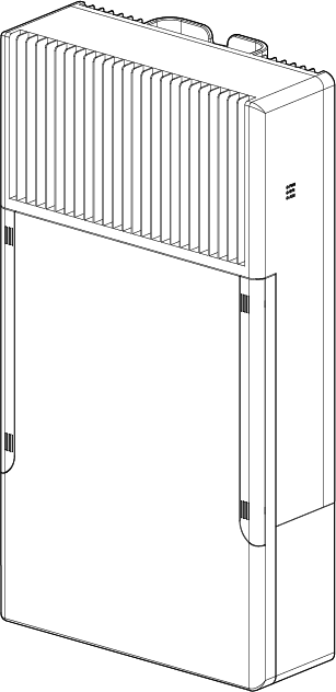
Appearance and Structure
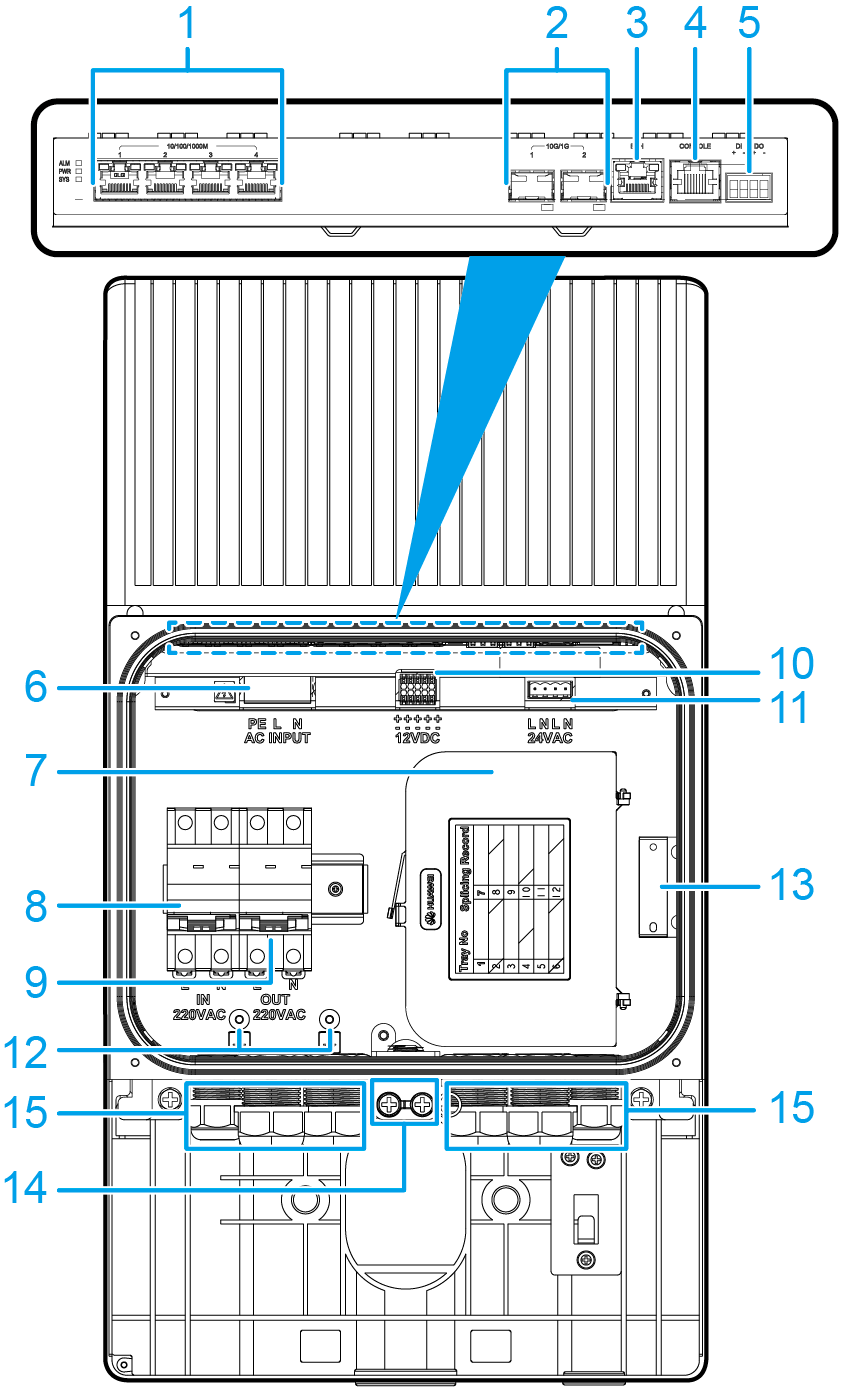
1 |
Four 10/100/1000BASE-T ports |
2 |
Two 10GE SFP+ ports Applicable modules and cables:
NOTE:
If one port uses a GPON optical module, the other port cannot be used at the same time. |
3 |
One ETH management port |
4 |
One console port |
5 |
Monitoring port
NOTE:
The monitoring port can be used to detect the status of a connected external device, such as the opening and closing of the maintenance compartment door. The monitoring port is used with a conductive cable. The minimum cross-sectional area of the conductor connected to a conductive cable is 0.3 mm2 or 22 AWG, and the maximum cross-sectional area of the conductor is 1.3 mm2 or 16 AWG. For details about how to use a monitoring port, see "Monitoring Interface Configuration" in the Configuration Guide - Device Management Configuration. |
6 |
220 V AC power input socket |
7 |
Fiber management tray (FMT) NOTE:
The FMT is optional. |
8 |
220 V AC power input circuit breaker NOTICE:
This circuit breaker is optional. Connect an external power cable to the 220 V AC power input circuit breaker when it is in use. An external power cable needs to be prepared onsite. Ensure that the wires of the external cable are correctly connected to the L and N sockets of a plug. The circuit breaker supports a maximum of 32 A input current and provides two 220 V AC outputs.
|
9 |
220 V AC power output circuit breaker NOTICE:
This circuit breaker is optional. The 220 V AC power output circuit breaker provides overcurrent protection only, and is only used for external power conversion. It supports a maximum of 10 A output current. The connected external devices need to provide certain surge protection capabilities. It is recommended that the surge protection capabilities for both differential and common modes be 20 kA. |
10 |
12 V DC power output socket NOTE:
The switch provides five 12 V DC outputs to external devices, such as strobe lights and non-PoE PTZ dome cameras. |
11 |
24 V AC power output socket NOTE:
The switch provides two 24 V AC outputs to external devices, such as strobe lights and non-PoE PTZ dome cameras. |
12 |
PE cable ground terminal NOTE:
It is used to ground a PE power cable for 220 V AC input or output. |
13 |
Door status sensor NOTE:
It reports an alarm when the maintenance compartment door of the switch is opened. |
14 |
Ground screw NOTE:
It is used to ground the switch. The ground cable needs to be purchased separately. |
15 |
Cable outlet |
- |
- |
Port Description
10/100/1000BASE-T port
10GE SFP+ port
Console port
ETH management port
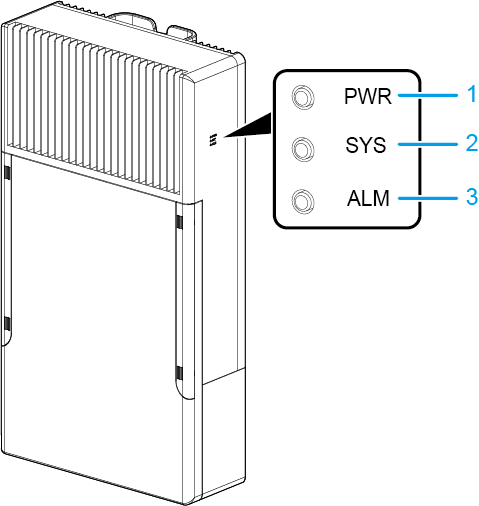
Indicator Description

No. |
Indicator |
Name |
Color |
Status |
Description |
|---|---|---|---|---|---|
1 |
PWR |
Power indicator |
- |
Steady off |
The switch is powered off. |
Green |
Steady on |
The switch is powered on and can communicate with the built-in power module properly. |
|||
Yellow |
Steady on |
The switch is powered on but cannot communicate with the built-in power module properly. |
|||
2 |
SYS |
System status indicator |
- |
Steady off |
The system is not running. |
Green |
Fast blinking |
The system is starting. |
|||
Green |
Steady on |
In the system startup preparation phase, the SYS indicator is steady green for no more than 30 seconds. |
|||
Green |
Slow blinking |
The system is running normally. |
|||
Red |
Steady on |
The system does not work normally after registration, or a temperature alarm has been generated. |
|||
3 |
ALM |
Alarm indicator |
- |
Steady off |
There is no AC input or power supply is normal. |
Red |
Steady on |
The power supply to the switch is abnormal. |
|||
4 |
- |
Service port indicator |
- |
Steady off |
The port is not connected or has been shut down. |
Green and yellow |
Steady on |
The port is connected. |
|||
Green and yellow |
Blinking |
The port is sending or receiving data. |
|||
5 |
- |
ETH port indicator |
- |
Steady off |
The ETH port is not connected. |
Green and yellow |
Steady on |
The ETH port is connected. |
|||
Green and yellow |
Blinking |
The port is sending or receiving data. |
Power Supply Configuration
The S5735-S4T2X-IA150G1 has a built-in power module and does not support pluggable power modules. The S5735-S4T2X-IA150G1 can be directly connected to an external 220 V AC power supply and provide power for external devices. Table 7 lists the power supply configurations of the S5735-S4T2X-IA150G1.
Power Supply Mode |
Available Power |
|---|---|
12 V DC |
Five 12 V DC outputs provide a total of 72 W power. The maximum power of a single output is 72 W. |
24 V AC |
Two 24 V AC outputs provide a total of 72 W power. The maximum power of a single output is 72 W. |

The five 12 V DC outputs and two 24 V AC outputs provides a combined total power output of 144 W.
Heat Dissipation
The S5735-S4T2X-IA150G1 has no fans and uses natural heat dissipation.
Technical Specifications
Table 8 lists technical specifications of the S5735-S4T2X-IA150G1.
Item |
Description |
|---|---|
Memory (RAM) |
1 GB |
Flash |
512 MB in total. To view the available flash memory size, run the display version command. |
Mean time between failures (MTBF) |
57.28 years |
Mean time to repair (MTTR) |
2 hours |
Availability |
> 0.99999 |
Service port surge protection |
±1.5 kV in differential mode, ±6 kV in common mode |
Power supply surge protection |
Surge current:
Surge:
|
Dimensions (H x W x D) |
550 mm x 300 mm x 135 mm (21.65 in. x 11.81 in. x 5.31 in.) |
Weight (including packaging) |
12.2 kg (26.9 lb) |
Stack ports |
Not supported |
RTC |
Not supported |
RPS |
Not supported |
PoE |
Not supported |
Rated voltage range |
220 V AC to 240 V AC, 50/60 Hz |
Maximum voltage range |
176 V AC to 264 V AC, 45 Hz to 66 Hz |
Maximum power consumption (100% throughput) |
29 W |
Typical power consumption (30% of traffic load)
|
28 W |
Operating temperature |
-40°C to +75°C (-40°F to 167°F)
NOTE:
–25ºC to +75ºC (–13ºF to +167ºF): sunshade needed; 400 LFM air velocity (minimum); GPON optical modules not supported –25ºC to +70ºC (–13ºF to +158ºF): sunshade needed; 200 LFM air velocity (minimum); GPON optical modules supported –30ºC to +60ºC (–22ºF to +140ºF): sunshade needed; 40 LFM air velocity (minimum); GPON optical modules supported –35ºC to +55ºC (–31ºF to +131ºF): sunshade needed; no requirement on the air velocity; GPON optical modules supported –35ºC to +45ºC (–31ºF to +113ºF): 1120 W/m2 solar radiation (maximum); no requirement on the air velocity –40ºC to –35ºC (–40ºF to –31ºF): At least four Ethernet electrical ports must be working. When the altitude is 1800-4000 m (5906-13123 ft.), the highest operating temperature reduces by 1°C (1.8°F) every time the altitude increases by 220 m (722 ft.). |
Storage temperature |
-40°C to +85°C (-40°F to +185°F) |
IP rating |
IP55 |
Noise under normal temperature (27°C, sound power) |
Noise-free (no fans) |
Relative humidity |
5% to 95%, noncondensing |
Operating altitude |
0-4000 m (0-13123 ft.) |
Product certification |
|
Part number |
02312NTA |