Example for Configuring AS_Path Filter
Networking Requirements
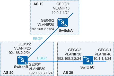
On the network shown in Figure 1, SwitchB establish EBGP connections with SwitchA and SwitchC. The user wants to disable the devices in AS 10 from communicating with devices in AS 30.
Configuration Roadmap
The configuration roadmap is as follows:
- Establish EBGP connections between SwitchA and SwitchB and between SwitchB and SwitchC and configure these devices to import direct routes so that the ASs can communicate with each other through these EBGP connections.
- Configure AS_Path filters on SwitchB and use filtering rules to prevent AS 20 from advertising routes of AS 30 to AS 10 or routes of AS 10 to AS 30.
Procedure
- Configure the VLAN to which each interface belongs.
# Configure SwitchA. The configurations of SwitchB and SwitchC are similar to the configuration of SwitchA.
<HUAWEI> system-view
[HUAWEI] sysname SwitchA
[SwitchA] vlan batch 10 20
[SwitchA] interface gigabitethernet 1/0/1
[SwitchA-GigabitEthernet0/0/1] port link-type trunk
[SwitchA-GigabitEthernet0/0/1] port trunk allow-pass vlan 10
[SwitchA-GigabitEthernet0/0/1] quit
[SwitchA] interface gigabitethernet 0/0/2
[SwitchA-GigabitEthernet0/0/2] port link-type trunk
[SwitchA-GigabitEthernet0/0/2] port trunk allow-pass vlan 20
[SwitchA-GigabitEthernet0/0/2] quit
- Assign an IP address to each VLANIF interface.
# Configure SwitchA. The configurations of SwitchB and SwitchC are similar to the configuration of SwitchA.
[SwitchA] interface vlanif 10
[SwitchA-Vlanif10] ip address 10.0.1.1 24
[SwitchA-Vlanif10] quit
[SwitchA] interface vlanif 20
[SwitchA-Vlanif20] ip address 192.168.2.1 24
[SwitchA-Vlanif20] quit
- Configure EBGP connections.
# Configure SwitchA.
[SwitchA] bgp 10
[SwitchA-bgp] router-id 172.16.1.1
[SwitchA-bgp] peer 192.168.2.2 as-number 20
[SwitchA-bgp] import-route direct
[SwitchA-bgp] quit
# Configure SwitchB.
[SwitchB] bgp 20
[SwitchB-bgp] router-id 172.16.2.2
[SwitchB-bgp] peer 192.168.2.1 as-number 10
[SwitchB-bgp] peer 192.168.3.2 as-number 30
[SwitchB-bgp] import-route direct
[SwitchB-bgp] quit
# Configure SwitchC.
[SwitchC] bgp 30
[SwitchC-bgp] router-id 172.16.3.3
[SwitchC-bgp] peer 192.168.3.1 as-number 20
[SwitchC-bgp] import-route direct
[SwitchC-bgp] quit
# Check the routing table advertised by SwitchB to peer 200.1.3.2. Take the routing table advertised by SwitchB to SwitchC as an example. You can find that SwitchB advertises the routes destined to the network segment between SwitchA and SwitchC.
[SwitchB] display bgp routing-table peer 192.168.3.2 advertised-routes

 BGP Local router ID is 172.16.2.2
 Status codes: * - valid, > - best, d - damped,
               h - history,  i - internal, s - suppressed, S - Stale
               Origin : i - IGP, e - EGP, ? - incomplete


 Total Number of Routes: 4
      Network            NextHop        MED        LocPrf    PrefVal Path/Ogn

 *>   10.0.1.0/24        192.168.3.1                           0      20 10?
 *>   10.1.1.0/24        192.168.3.1                           0      20 30?
 *>   192.168.2.0        192.168.3.1     0                     0      20?
 *>   192.168.3.0        192.168.3.1     0                     0      20?
Check the routing table of SwitchC. You can find that SwitchC learns the routes advertised by SwitchB.
[SwitchC] display bgp routing-table BGP Local router ID is 172.16.3.3 Status codes: * - valid, > - best, d - damped, h - history, i - internal, s - suppressed, S - Stale Origin : i - IGP, e - EGP, ? - incomplete Total Number of Routes: 9 Network NextHop MED LocPrf PrefVal Path/Ogn *> 10.0.1.0/24 192.168.3.1 0 20 10? *> 10.1.1.0/24 0.0.0.0 0 0 ? *> 10.1.1.1/32 0.0.0.0 0 0 ? *> 127.0.0.0 0.0.0.0 0 0 ? *> 127.0.0.1/32 0.0.0.0 0 0 ? *> 192.168.2.0 192.168.3.1 0 0 20? *> 192.168.3.0 0.0.0.0 0 0 ? 192.168.3.1 0 0 20? *> 192.168.3.2/32 0.0.0.0 0 0 ? - Configure the AS_Path filter on SwitchB and apply the filter on
the outbound interface of SwitchB.
# Create AS_Path filter 1, denying the passing of routes carrying AS 30. The regular expression "_30_" indicates any AS list that contains AS 30 and ".*" matches any character.
[SwitchB] ip as-path-filter path-filter1 deny _30_
[SwitchB] ip as-path-filter path-filter1 permit .*
# Create AS_Path filter 2, denying the passing of routes carrying AS 10. The regular expression "_10_" indicates any AS list that contains AS 10 and "*" matches any character.
[SwitchB] ip as-path-filter path-filter2 deny _10_
[SwitchB] ip as-path-filter path-filter2 permit .*
# Apply the AS_Path filter on two outbound interfaces of SwitchB.
[SwitchB] bgp 20
[SwitchB-bgp] peer 192.168.2.1 as-path-filter path-filter1 export
[SwitchB-bgp] peer 192.168.3.2 as-path-filter path-filter2 export
[SwitchB-bgp] quit
- Check the routing table advertised by SwitchB, and you can find that
the advertised routes to the network segment between SwitchA and SwitchC do not exist. Take the
route advertised by SwitchB to SwitchC as an example.
[SwitchB] display bgp routing-table peer 192.168.3.2 advertised-routes

 BGP Local router ID is 172.16.2.2
 Status codes: * - valid, > - best, d - damped,
               h - history,  i - internal, s - suppressed, S - Stale
               Origin : i - IGP, e - EGP, ? - incomplete


 Total Number of Routes: 2
      Network            NextHop        MED        LocPrf    PrefVal Path/Ogn

 *>   192.168.2.0        192.168.3.1     0                     0      20?
 *>   192.168.3.0        192.168.3.1     0                     0      20?
Similarly, the BGP routing table of SwitchC does not have the two routes.
[SwitchC] display bgp routing-table

 BGP Local router ID is 172.16.3.3
 Status codes: * - valid, > - best, d - damped,
               h - history,  i - internal, s - suppressed, S - Stale
               Origin : i - IGP, e - EGP, ? - incomplete

 Total Number of Routes: 8
      Network            NextHop        MED        LocPrf    PrefVal Path/Ogn

 *>   10.1.1.0/24        0.0.0.0         0                     0      ?
 *>   10.1.1.1/32        0.0.0.0         0                     0      ?
 *>   127.0.0.0          0.0.0.0         0                     0      ?
 *>   127.0.0.1/32       0.0.0.0         0                     0      ?
 *>   192.168.2.0        192.168.3.1     0                     0      20?
 *>   192.168.3.0        0.0.0.0         0                     0      ?
                         192.168.3.1     0                     0      20?
 *>   192.168.3.2/32     0.0.0.0         0                     0      ?
Check the routing table advertised by SwitchB, and you can find that advertised routes directly connected to SwitchA and SwitchC do not exist. Take the route advertised by SwitchB to SwitchA as an example.
[SwitchB] display bgp routing-table peer 192.168.2.1 advertised-routes

 BGP Local router ID is 172.16.2.2
 Status codes: * - valid, > - best, d - damped,
               h - history,  i - internal, s - suppressed, S - Stale
               Origin : i - IGP, e - EGP, ? - incomplete


 Total Number of Routes: 2
      Network            NextHop        MED        LocPrf    PrefVal Path/Ogn

 *>   192.168.2.0        192.168.2.2     0                     0      20?
 *>   192.168.3.0        192.168.2.2     0                     0      20?
Similarly, the BGP routing table of SwitchA does not have the two routes.
[SwitchA] display bgp routing-table

 BGP Local router ID is 172.16.1.1
 Status codes: * - valid, > - best, d - damped,
               h - history,  i - internal, s - suppressed, S - Stale
               Origin : i - IGP, e - EGP, ? - incomplete

 Total Number of Routes: 8
      Network            NextHop        MED        LocPrf    PrefVal Path/Ogn

 *>   10.0.1.0/24        0.0.0.0         0                     0      ?
 *>   10.0.1.1/32        0.0.0.0         0                     0      ?
 *>   127.0.0.0          0.0.0.0         0                     0      ?
 *>   127.0.0.1/32       0.0.0.0         0                     0      ?
 *>   192.168.2.0        0.0.0.0         0                     0      ?
                         192.168.2.2     0                     0      20?
 *>   192.168.2.1/32     0.0.0.0         0                     0      ?
 *>   192.168.3.0        192.168.2.2     0                     0      20?
Configuration Files
SwitchA configuration file
#
sysname SwitchA
#
vlan batch 10 20
#
interface Vlanif10
 ip address 10.0.1.1 255.255.255.0
#
interface Vlanif20
 ip address 192.168.2.1 255.255.255.0
#
interface GigabitEthernet0/0/1
 port link-type trunk
 port trunk allow-pass vlan 10
#
interface GigabitEthernet0/0/2
 port link-type trunk
 port trunk allow-pass vlan 20
#
bgp 10
 router-id 172.16.1.1
 peer 192.168.2.2 as-number 20
 #
 ipv4-family unicast
  undo synchronization
  import-route direct
  peer 192.168.2.2 enable
#
return
SwitchB configuration file
#
sysname SwitchB
#
vlan batch 20 30
#
interface Vlanif20
 ip address 192.168.2.2 255.255.255.0
#
interface Vlanif30
 ip address 192.168.3.1 255.255.255.0
#
interface GigabitEthernet0/0/1
 port link-type trunk
 port trunk allow-pass vlan 30
#
interface GigabitEthernet0/0/2
 port link-type trunk
 port trunk allow-pass vlan 20
#
bgp 20
 router-id 172.16.2.2
 peer 192.168.2.1 as-number 10
 peer 192.168.3.2 as-number 30
 #
 ipv4-family unicast
  undo synchronization
  import-route direct
  peer 192.168.2.1 enable
  peer 192.168.2.1 as-path-filter path-filter1 export
  peer 192.168.3.2 enable
  peer 192.168.3.2 as-path-filter path-filter2 export
#
 ip as-path-filter path-filter1 deny _30_
 ip as-path-filter path-filter1 permit .*
 ip as-path-filter path-filter2 deny _10_
 ip as-path-filter path-filter2 permit .*
#
return
SwitchC configuration file
#
sysname SwitchC
#
vlan batch 30 40
#
interface Vlanif30
 ip address 192.168.3.2 255.255.255.0
#
interface Vlanif40
 ip address 10.1.1.1 255.255.255.0
#
interface GigabitEthernet0/0/1
 port link-type trunk
 port trunk allow-pass vlan 40
#
interface GigabitEthernet0/0/2
 port link-type trunk
 port trunk allow-pass vlan 30
#
bgp 30
 router-id 172.16.3.3
 peer 192.168.3.1 as-number 20
 #
 ipv4-family unicast
  undo synchronization
  import-route direct
  peer 192.168.3.1 enable
#
return