Example for Configuring MED Attributes to Control BGP Route Selection
Networking Requirements
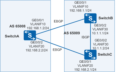
As shown in Figure 1, BGP is configured on all switches; SwitchA resides in AS 65008; SwitchB and SwitchC reside in AS 65009. EBGP connections are established between SwitchA and SwitchB, and between SwitchA and SwitchC. An IBGP connection is established between SwitchB and SwitchC. After a period, traffic from AS 65008 to AS 65009 needs to first pass through SwitchC.

In this scenario, ensure that all connected interfaces have STP disabled. If STP is enabled and VLANIF interfaces of switches are used to construct a Layer 3 ring network, an interface on the network will be blocked. As a result, Layer 3 services on the network cannot run normally.
Configuration Roadmap
The configuration roadmap is as follows:
- Establish EBGP connections between SwitchA and SwitchB and between SwitchA and SwitchC, and establish an IBGP connection between SwitchB and SwitchC.
- Apply a routing policy to increase the MED value of the route sent by SwitchB to SwitchA so that SwitchA will send traffic to AS 65009 through SwitchC.
Procedure
- Create VLANs and add interfaces to the corresponding VLANs.
# Configure SwitchA. The configurations of SwitchB and SwitchC are similar to the configuration of SwitchA.
<HUAWEI> system-view
[HUAWEI] sysname SwitchA
[SwitchA] vlan batch 10 20
[SwitchA] interface gigabitethernet 0/0/1
[SwitchA-GigabitEthernet0/0/1] port link-type trunk
[SwitchA-GigabitEthernet0/0/1] port trunk allow-pass vlan 10
[SwitchA-GigabitEthernet0/0/1] quit
[SwitchA] interface gigabitethernet 0/0/2
[SwitchA-GigabitEthernet0/0/2] port link-type trunk
[SwitchA-GigabitEthernet0/0/2] port trunk allow-pass vlan 20
[SwitchA-GigabitEthernet0/0/2] quit
- Assign an IP address to each VLANIF interface.
# Configure SwitchA. The configurations of SwitchB and SwitchC are similar to the configuration of SwitchA.
[SwitchA] interface vlanif 10
[SwitchA-Vlanif10] ip address 192.168.1.2 24
[SwitchA-Vlanif10] quit
[SwitchA] interface vlanif 20
[SwitchA-Vlanif20] ip address 192.168.2.2 24
[SwitchA-Vlanif20] quit
- Establish a BGP connection.
# Configure SwitchA.
[SwitchA] bgp 65008
[SwitchA-bgp] router-id 172.16.1.1
[SwitchA-bgp] peer 192.168.1.1 as-number 65009
[SwitchA-bgp] peer 192.168.2.1 as-number 65009
[SwitchA-bgp] quit
# Configure SwitchB.
[SwitchB] bgp 65009
[SwitchB-bgp] router-id 172.16.2.2
[SwitchB-bgp] peer 192.168.1.2 as-number 65008
[SwitchB-bgp] peer 10.1.1.2 as-number 65009
[SwitchB-bgp] ipv4-family unicast
[SwitchB-bgp-af-ipv4] network 10.1.1.0 255.255.255.0
[SwitchB-bgp-af-ipv4] quit
[SwitchB-bgp] quit
# Configure SwitchC.
[SwitchC] bgp 65009
[SwitchC-bgp] router-id 172.16.3.3
[SwitchC-bgp] peer 192.168.2.2 as-number 65008
[SwitchC-bgp] peer 10.1.1.1 as-number 65009
[SwitchC-bgp] ipv4-family unicast
[SwitchC-bgp-af-ipv4] network 10.1.1.0 255.255.255.0
[SwitchC-bgp-af-ipv4] quit
[SwitchC-bgp] quit
# Check the routing table of SwitchA.
[SwitchA] display bgp routing-table

 BGP Local router ID is 172.16.1.1
 Status codes: * - valid, > - best, d - damped,
               h - history,  i - internal, s - suppressed, S - Stale
               Origin : i - IGP, e - EGP, ? - incomplete


 Total Number of Routes: 2
      Network            NextHop        MED        LocPrf    PrefVal Path/Ogn


 *>   10.1.1.0/24       192.168.1.1     0                     0       65009i
 *                      192.168.2.1     0                     0       65009i
According to the routing table, you can view that there are two valid routes destined for 10.1.1.0/24. The route whose next hop is 192.168.1.1 is the optimal route because the router ID of SwitchB is smaller.
- Configure load balancing.
# Configure SwitchA.
[SwitchA] bgp 65008
[SwitchA-bgp] ipv4-family unicast
[SwitchA-bgp-af-ipv4] maximum load-balancing 2
[SwitchA-bgp-af-ipv4] quit
[SwitchA-bgp] quit
# Check the routing table of SwitchA.
[SwitchA] display bgp routing-table

 BGP Local router ID is 172.16.1.1
 Status codes: * - valid, > - best, d - damped,
               h - history,  i - internal, s - suppressed, S - Stale
               Origin : i - IGP, e - EGP, ? - incomplete

 Total Number of Routes: 2
      Network            NextHop        MED        LocPrf    PrefVal Path/Ogn

 *>   10.1.1.0/24        192.168.1.1     0                     0      65009i
 *>                      192.168.2.1     0                     0      65009i
According to the routing table, you can view that the BGP route 10.1.1.0/24 has two next hops that are 192.168.1.1 and 192.168.2.1. Both of them are optimal routes.
- Set the MED.
# Set the MED sent from SwitchB to SwitchA through the policy.
[SwitchB] route-policy 10 permit node 10
[SwitchB-route-policy] apply cost 100
[SwitchB-route-policy] quit
[SwitchB] bgp 65009
[SwitchB-bgp] peer 192.168.1.2 route-policy 10 export
# Check the routing table of SwitchA.
[SwitchA] display bgp routing-table

 BGP Local router ID is 172.16.1.1
 Status codes: * - valid, > - best, d - damped,
               h - history,  i - internal, s - suppressed, S - Stale
               Origin : i - IGP, e - EGP, ? - incomplete
 Total Number of Routes: 2
      Network            NextHop        MED        LocPrf    PrefVal Path/Ogn

 *>   10.1.1.0/24        192.168.2.1     0                     0      65009i
 *                       192.168.1.1     100                   0      65009i
According to the routing table, you can view that the MED of the next hop 192.168.1.1 (SwitchB) is 100, and that of the next hop 192.168.2.1 is 0. Therefore, the route with the smaller MED is selected.
Configuration Files
SwitchA configuration file
#
sysname SwitchA
#
vlan batch 10 20
#
interface Vlanif10
 ip address 192.168.1.2 255.255.255.0
#
interface Vlanif20
 ip address 192.168.2.2 255.255.255.0
#
interface GigabitEthernet0/0/1
 port link-type trunk
 port trunk allow-pass vlan 10
#
interface GigabitEthernet0/0/2
 port link-type trunk
 port trunk allow-pass vlan 20
#
bgp 65008
 router-id 172.16.1.1
 peer 192.168.1.1 as-number 65009
 peer 192.168.2.1 as-number 65009
 #
 ipv4-family unicast
  undo synchronization
  maximum load-balancing 2
  peer 192.168.1.1 enable
  peer 192.168.2.1 enable
#
return
SwitchB configuration file
#
sysname SwitchB
#
vlan batch 10 30
#
interface Vlanif10
 ip address 192.168.1.1 255.255.255.0
#
interface Vlanif30
 ip address 10.1.1.1 255.255.255.0
#
interface GigabitEthernet0/0/1
 port link-type trunk
 port trunk allow-pass vlan 10
#
interface GigabitEthernet0/0/2
 port link-type trunk
 port trunk allow-pass vlan 30
#
bgp 65009
 router-id 172.16.2.2
 peer 10.1.1.2 as-number 65009
 peer 192.168.1.2 as-number 65008
 #
 ipv4-family unicast
  undo synchronization
  network 10.1.1.0 255.255.255.0
  peer 10.1.1.2 enable
  peer 192.168.1.2 enable
  peer 192.168.1.2 route-policy 10 export
#
route-policy 10 permit node 10
 apply cost 100
#
return
SwitchC configuration file
#
sysname SwitchC
#
vlan batch 20 30
#
interface Vlanif20
 ip address 192.168.2.1 255.255.255.0
#
interface Vlanif30
 ip address 10.1.1.2 255.255.255.0
#
interface GigabitEthernet0/0/1
 port link-type trunk
 port trunk allow-pass vlan 20
#
interface GigabitEthernet0/0/2
 port link-type trunk
 port trunk allow-pass vlan 30
#
bgp 65009
 router-id 172.16.3.3
 peer 10.1.1.1 as-number 65009
 peer 192.168.2.2 as-number 65008
 #
 ipv4-family unicast
  undo synchronization
  network 10.1.1.0 255.255.255.0
  peer 10.1.1.1 enable
  peer 192.168.2.2 enable
#
return