Example for Configuring a BGP Route Reflector
Networking Requirements
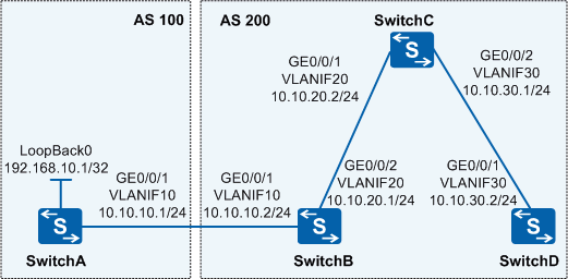
In Figure 1, four switches belong to two ASs, SwitchA and SwitchB establish an EBGP neighbor relationship, and SwitchC establishes an IBGP neighbor relationship with SwitchB and SwitchD. To prevent IBGP fully meshed connections and simplify network configurations, the user requires that devices in the two ASs communicate when no IBGP connection is established between SwitchB and SwitchD.
Configuration Roadmap
The configuration roadmap is as follows:
Configure basic BGP functions to allow BGP neighbors to communicate.
Configure SwitchC as an RR and configure SwitchB and SwitchD as two clients of the RR. Subsequently, SwitchB and SwitchD can learn the routes advertised by SwitchA without establishing an IBGP connection, simplifying configurations.
Procedure
- Add interfaces to VLANs.
# Configure SwitchA. The configurations of SwitchB, SwitchC, and SwitchD are similar to the configuration of SwitchA, and are not mentioned here.
<HUAWEI> system-view
[HUAWEI] sysname SwitchA
[SwitchA] vlan batch 10
[SwitchA] interface gigabitethernet 0/0/1
[SwitchA-GigabitEthernet0/0/1] port link-type trunk
[SwitchA-GigabitEthernet0/0/1] port trunk allow-pass vlan 10
[SwitchA-GigabitEthernet0/0/1] quit
- Configure IP addresses for interfaces and set the IP address
of LoopBack0 on SwitchA as the destination IP address of a ping test.
# Configure SwitchA. The configurations of SwitchB, SwitchC, and SwitchD are similar to the configuration of SwitchA, and are not mentioned here.
[SwitchA] interface vlanif 10
[SwitchA-Vlanif10] ip address 10.10.10.1 24
[SwitchA-Vlanif10] quit
[SwitchA] interface LoopBack 0
[SwitchA-LoopBack0] ip address 192.168.10.1 32
[SwitchA-LoopBack0] quit
- Configure basic BGP functions and advertise direct network
segments in the BGP processes of the four switches.
# Configure SwitchA.
[SwitchA] bgp 100
[SwitchA-bgp] router-id 10.1.1.1
[SwitchA-bgp] peer 10.10.10.2 as-number 200
[SwitchA-bgp] ipv4-family unicast
[SwitchA-bgp-af-ipv4] network 192.168.10.1 32
[SwitchA-bgp-af-ipv4] network 10.10.10.0 24
[SwitchA-bgp-af-ipv4] quit
[SwitchA-bgp] quit
# Configure SwitchB.
[SwitchB] bgp 200
[SwitchB-bgp] router-id 10.2.2.2
[SwitchB-bgp] peer 10.10.10.1 as-number 100
[SwitchB-bgp] peer 10.10.20.2 as-number 200
[SwitchB-bgp] ipv4-family unicast
[SwitchB-bgp-af-ipv4] network 10.10.10.0 24
[SwitchB-bgp-af-ipv4] network 10.10.20.0 24
[SwitchB-bgp-af-ipv4] quit
[SwitchB-bgp] quit
# Configure SwitchC.
[SwitchC] bgp 200
[SwitchC-bgp] router-id 10.3.3.3
[SwitchC-bgp] peer 10.10.20.1 as-number 200
[SwitchC-bgp] peer 10.10.30.2 as-number 200
[SwitchC-bgp] ipv4-family unicast
[SwitchC-bgp-af-ipv4] network 10.10.20.0 24
[SwitchC-bgp-af-ipv4] network 10.10.30.0 24
[SwitchC-bgp-af-ipv4] quit
[SwitchC-bgp] quit
# Configure SwitchD.
[SwitchD] bgp 200
[SwitchD-bgp] router-id 10.4.4.4
[SwitchD-bgp] peer 10.10.30.1 as-number 200
[SwitchD-bgp] ipv4-family unicast
[SwitchD-bgp-af-ipv4] network 10.10.30.0 24
[SwitchD-bgp-af-ipv4] quit
[SwitchD-bgp] quit
- Configure an RR.
# Configure SwitchC as an RR and configure SwitchB and SwitchD as two clients of the RR.
[SwitchC] bgp 200
[SwitchC-bgp] ipv4-family unicast
[SwitchC-bgp-af-ipv4] peer 10.10.20.1 reflect-client
[SwitchC-bgp-af-ipv4] peer 10.10.30.2 reflect-client
[SwitchC-bgp-af-ipv4] quit
[SwitchC-bgp] quit
- Verify the configuration.
# Check the BGP routing table of SwitchB.
[SwitchB] display bgp routing-table 192.168.10.1 32

 BGP local router ID : 10.2.2.2
 Local AS number : 200
 Paths:   1 available, 1 best, 1 select
 BGP routing table entry information of 192.168.10.1/32:
 From: 10.10.10.1 (10.1.1.1)
 Route Duration: 00h34m09s
 Direct Out-interface: Vlanif10
 Original nexthop: 10.10.10.1
 Qos information : 0x0
 AS-path 100, origin igp, MED 0, pref-val 0, valid, external, best, select, active, pre 255
 Advertised to such 1 peers:
    10.10.20.2
The command output shows that SwitchB has learned and advertised the route 192.168.10.1/32 to SwitchC.
# Check the BGP routing table of SwitchC.
[SwitchC] display bgp routing-table 192.168.10.1 32

 BGP local router ID : 10.3.3.3
 Local AS number : 200
 Paths:   1 available, 1 best, 1 select
 BGP routing table entry information of 192.168.10.1/32:
 RR-client route.
 From: 10.10.20.1 (10.2.2.2)
 Route Duration: 00h34m17s
 Relay IP Nexthop: 10.10.20.1
 Relay IP Out-Interface: Vlanif20
 Original nexthop: 10.10.10.1
 Qos information : 0x0
 AS-path 100, origin igp, MED 0, localpref 100, pref-val 0, valid, internal, best, select, active, pre 255
 Advertised to such 2 peers:
    10.10.20.1
    10.10.30.2
The command output shows that SwitchC has learned and advertised the route 192.168.10.1/32 to its two clients SwitchB and SwitchD.
# Check the BGP routing table of SwitchD.
[SwitchD] display bgp routing-table 192.168.10.1 32

 BGP local router ID : 10.4.4.4
 Local AS number : 200
 Paths:   1 available, 1 best, 1 select
 BGP routing table entry information of 192.168.10.1/32:
 From: 10.10.30.1 (10.3.3.3)
 Route Duration: 00h34m25s
 Relay IP Nexthop: 10.10.30.1
 Relay IP Out-Interface: Vlanif30
 Original nexthop: 10.10.10.1
 Qos information : 0x0
 AS-path 100, origin igp, MED 0, localpref 100, pref-val 0, valid, internal, best, select, active, pre 255
 Originator:  10.2.2.2
 Cluster list: 10.3.3.3
 Not advertised to any peer yet
The command output shows that SwitchD has learned from SwitchC the route 192.168.10.1/32 advertised by SwitchA.
# On SwitchD, ping the IP address of LoopBack0 on SwitchA to test route reachability.
[SwitchD] ping 192.168.10.1
  PING 192.168.10.1: 56  data bytes, press CTRL_C to break
    Reply from 192.168.10.1: bytes=56 Sequence=1 ttl=255 time=31 ms
    Reply from 192.168.10.1: bytes=56 Sequence=2 ttl=255 time=16 ms
    Reply from 192.168.10.1: bytes=56 Sequence=3 ttl=255 time=40 ms
    Reply from 192.168.10.1: bytes=56 Sequence=4 ttl=255 time=30 ms
    Reply from 192.168.10.1: bytes=56 Sequence=5 ttl=255 time=26 ms

  --- 192.168.10.1 ping statistics ---
    5 packet(s) transmitted
    5 packet(s) received
    0.00% packet loss
    round-trip min/avg/max = 70/84/100 ms
The command output shows that SwitchD pings the IP address of LoopBack0 on SwitchA successfully, indicating that routes to SwitchA are reachable.
Configuration Files
SwitchA configuration file
#
sysname SwitchA
#
vlan batch 10
#
interface Vlanif10
 ip address 10.10.10.1 255.255.255.0
#
interface GigabitEthernet0/0/1
 port link-type trunk
 port trunk allow-pass vlan 10
#
interface LoopBack0
 ip address 192.168.10.1 255.255.255.255
#
bgp 100
 router-id 10.1.1.1
 peer 10.10.10.2 as-number 200
 #
 ipv4-family unicast
  undo synchronization
  network 10.10.10.0 255.255.255.0
  network 192.168.10.1 255.255.255.255
  peer 10.10.10.2 enable
#
return
SwitchB configuration file
#
sysname SwitchB
#
vlan batch 10 20
#
interface Vlanif10
 ip address 10.10.10.2 255.255.255.0
#
interface Vlanif20
 ip address 10.10.20.1 255.255.255.0
#
interface GigabitEthernet0/0/1
 port link-type trunk
 port trunk allow-pass vlan 10
#
interface GigabitEthernet0/0/2
 port link-type trunk
 port trunk allow-pass vlan 20
#
bgp 200
 router-id 10.2.2.2
 peer 10.10.10.1 as-number 100
 peer 10.10.20.2 as-number 200
 #
 ipv4-family unicast
  undo synchronization
  network 10.10.10.0 255.255.255.0
  network 10.10.20.0 255.255.255.0
  peer 10.10.10.1 enable
  peer 10.10.20.2 enable
#
return
SwitchC configuration file
#
sysname SwitchC
#
vlan batch 20 30
#
interface Vlanif20
 ip address 10.10.20.2 255.255.255.0
#
interface Vlanif30
 ip address 10.10.30.1 255.255.255.0
#
interface GigabitEthernet0/0/1
 port link-type trunk
 port trunk allow-pass vlan 20
#
interface GigabitEthernet0/0/2
 port link-type trunk
 port trunk allow-pass vlan 30
#
bgp 200
 router-id 10.3.3.3
 peer 10.10.20.1 as-number 200
 peer 10.10.30.2 as-number 200
 #
 ipv4-family unicast
  undo synchronization
  network 10.10.20.0 255.255.255.0
  network 10.10.30.0 255.255.255.0
  peer 10.10.20.1 enable
  peer 10.10.20.1 reflect-client
  peer 10.10.30.2 enable
  peer 10.10.30.2 reflect-client
#
return
SwitchD configuration file
#
sysname SwitchD
#
vlan batch 30
#
interface Vlanif30
 ip address 10.10.30.2 255.255.255.0
#
interface GigabitEthernet0/0/1
 port link-type trunk
 port trunk allow-pass vlan 30
#
bgp 200
 router-id 10.4.4.4
 peer 10.10.30.1 as-number 200
 #
 ipv4-family unicast
  undo synchronization
  network 10.10.30.0 255.255.255.0
  peer 10.10.30.1 enable
#
return