Example for Configuring IS-IS Load Balancing
Networking Requirements
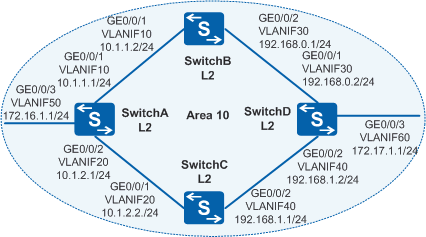
As shown in Figure 1, switches run IS-IS to implement IP interworking. Congestion of the network from SwitchA to destination address 172.17.1.0/24 needs to be relieved to improve network resource efficiency.

In this scenario, ensure that all connected interfaces have STP disabled. If STP is enabled and VLANIF interfaces of switches are used to construct a Layer 3 ring network, an interface on the network will be blocked. As a result, Layer 3 services on the network cannot run normally.
Configuration Roadmap
- Configure basic IS-IS functions on each switch to implement IP interworking.
- Configure load balancing to balance traffic from SwitchA to SwitchD between SwitchB and SwitchC.
Procedure
- Configure VLANs that the related interfaces belong to.
# Configure SwitchA. The configurations of SwitchB, SwitchC, and SwitchD are similar to the configuration of SwitchA.
<HUAWEI> system-view
[HUAWEI] sysname SwitchA
[SwitchA] vlan batch 10 20 50
[SwitchA] interface gigabitethernet 0/0/1
[SwitchA-GigabitEthernet0/0/1] port link-type trunk
[SwitchA-GigabitEthernet0/0/1] port trunk allow-pass vlan 10
[SwitchA-GigabitEthernet0/0/1] quit
[SwitchA] interface gigabitethernet 0/0/2
[SwitchA-GigabitEthernet0/0/2] port link-type trunk
[SwitchA-GigabitEthernet0/0/2] port trunk allow-pass vlan 20
[SwitchA-GigabitEthernet0/0/2] quit
[SwitchA] interface gigabitethernet 0/0/3
[SwitchA-GigabitEthernet0/0/3] port link-type trunk
[SwitchA-GigabitEthernet0/0/3] port trunk allow-pass vlan 50
[SwitchA-GigabitEthernet0/0/3] quit
- Assign an IP address to each VLANIF interface.
# Configure SwitchA. The configurations of SwitchB, SwitchC, and SwitchD are similar to the configuration of SwitchA.
[SwitchA] interface vlanif 10
[SwitchA-Vlanif10] ip address 10.1.1.1 24
[SwitchA-Vlanif10] quit
[SwitchA] interface vlanif 20
[SwitchA-Vlanif20] ip address 10.1.2.1 24
[SwitchA-Vlanif20] quit
[SwitchA] interface vlanif 50
[SwitchA-Vlanif50] ip address 172.16.1.1 24
[SwitchA-Vlanif50] quit
- Configure basic IS-IS functions.
# Configure SwitchA. The configurations of SwitchB, SwitchC, and SwitchD are similar to the configuration of SwitchA.
[SwitchA] isis 1
[SwitchA-isis-1] is-level level-2
[SwitchA-isis-1] network-entity 10.0000.0000.0001.00
[SwitchA-isis-1] quit
[SwitchA] interface vlanif 10
[SwitchA-Vlanif10] isis enable 1
[SwitchA-Vlanif10] quit
[SwitchA] interface vlanif 20
[SwitchA-Vlanif20] isis enable 1
[SwitchA-Vlanif20] quit
[SwitchA] interface vlanif 50
[SwitchA-Vlanif50] isis enable 1
[SwitchA-Vlanif50] quit
- Set the number of equal-cost routes for load balancing to 1 on SwitchA.
[SwitchA] isis 1
[SwitchA-isis-1] maximum load-balancing 1
[SwitchA-isis-1] quit
# View the routing table of SwitchA.
[SwitchA] display isis route

                         Route information for ISIS(1)
                         -----------------------------

                        ISIS(1) Level-2 Forwarding Table
                        --------------------------------

 IPV4 Destination     IntCost   ExtCost ExitInterface    NextHop        Flags
-------------------------------------------------------------------------------
 172.17.1.0/24        30         NULL     Vlanif10       10.1.1.2       A/-/-/-
 172.16.1.0/24        10         NULL     Vlanif50       Direct         D/-/L/-
 192.168.0.0/24       20         NULL     Vlanif10       10.1.1.2       A/-/-/-
 192.168.1.0/24       20         NULL     Vlanif20       10.1.2.2       A/-/-/-
 10.1.1.0/24          10         NULL     Vlanif10       Direct         D/-/L/-
 10.1.2.0/24          10         NULL     Vlanif20       Direct         D/-/L/-
      Flags: D-Direct, A-Added to URT, L-Advertised in LSPs, S-IGP Shortcut,
                               U-Up/Down Bit Set
As shown in the routing table, when the maximum number of equal-cost routes for load balancing is set to 1, IS-IS selects 10.1.1.2 as the next hop to the destination network 172.17.1.0. This is because SwitchB has a smaller system ID.
- Restore the default number of equal-cost routes for load balancing on SwitchA.
[SwitchA] isis 1
[SwitchA-isis-1] undo maximum load-balancing
[SwitchA-isis-1] quit
# View the routing table of SwitchA.
[SwitchA] display isis route

                         Route information for ISIS(1)
                         -----------------------------

                        ISIS(1) Level-2 Forwarding Table
                        --------------------------------

 IPV4 Destination     IntCost   ExtCost ExitInterface    NextHop        Flags
-------------------------------------------------------------------------------
 172.17.1.0/24        30        NULL     Vlanif10        10.1.1.2       A/-/-/-
                                         Vlanif20        10.1.2.2
 172.16.1.0/24        10        NULL     Vlanif50        Direct         D/-/L/-
 192.168.0.0/24       20        NULL     Vlanif10        10.1.1.2       A/-/-/-
 192.168.1.0/24       20        NULL     Vlanif20        10.1.2.2       A/-/-/-
 10.1.1.0/24          10        NULL     Vlanif10        Direct         D/-/L/-
 10.1.2.0/24          10        NULL     Vlanif20        Direct         D/-/L/-
     Flags: D-Direct, A-Added to URT, L-Advertised in LSPs, S-IGP Shortcut,
                               U-Up/Down Bit Set
As shown in the routing table, the number of equal-cost routes for load balancing is restored to the default value. Both the next hops of SwitchA, 10.1.1.2 (SwitchB) and 10.1.2.2 (SwitchC) now become valid.
- (Optional) Set the preference for equal-cost routes on SwitchA.
[SwitchA] isis
[SwitchA-isis-1] nexthop 10.1.2.2 weight 1
[SwitchA-isis-1] quit
- Verify the configuration.
# View the routing table of SwitchA.
[SwitchA] display isis route

                         Route information for ISIS(1)
                         -----------------------------

                        ISIS(1) Level-2 Forwarding Table
                        --------------------------------

 IPV4 Destination     IntCost    ExtCost ExitInterface   NextHop         Flags
-------------------------------------------------------------------------------
 172.17.1.0/24        30         NULL     Vlanif20       10.1.2.2        A/-/-/-
 172.16.1.0/24        10         NULL     Vlanif50       Direct          D/-/L/-
 192.168.0.0/24       20         NULL     Vlanif10       10.1.1.2        A/-/-/-
 192.168.1.0/24       20         NULL     Vlanif20       10.1.2.2        A/-/-/-
 10.1.1.0/24          10         NULL     Vlanif10       Direct          D/-/L/-
 10.1.2.0/24          10         NULL     Vlanif20       Direct          D/-/L/-
      Flags: D-Direct, A-Added to URT, L-Advertised in LSPs, S-IGP Shortcut,
                               U-Up/Down Bit Set
As shown in the routing table, the preference of the next hop 10.1.2.2 (SwitchC) with the weight as 1, is higher than that of 10.1.1.2 (SwitchB), after the weight is set for equal-cost routes. Therefore, IS-IS selects route with the next hop 10.1.2.2 as the optimal route.
Configuration Files
SwitchA configuration file
#
sysname SwitchA
#
vlan batch 10 20 50
#
isis 1
 is-level level-2
 network-entity 10.0000.0000.0001.00
 nexthop 10.1.2.2 weight 1
#
interface Vlanif10
 ip address 10.1.1.1 255.255.255.0
 isis enable 1
#
interface Vlanif20
 ip address 10.1.2.1 255.255.255.0
 isis enable 1
#
interface Vlanif50
 ip address 172.16.1.1 255.255.255.0
 isis enable 1
#
interface GigabitEthernet0/0/1
 port link-type trunk
 port trunk allow-pass vlan 10
#
interface GigabitEthernet0/0/2
 port link-type trunk
 port trunk allow-pass vlan 20
#
interface GigabitEthernet0/0/3
 port link-type trunk
 port trunk allow-pass vlan 50
#
return
SwitchB configuration file
#
sysname SwitchB
#
vlan batch 10 30
#
isis 1
 is-level level-2
 network-entity 10.0000.0000.0002.00
#
interface Vlanif10
 ip address 10.1.1.2 255.255.255.0
 isis enable 1
#
interface Vlanif30
 ip address 192.168.0.1 255.255.255.0
 isis enable 1
#
interface GigabitEthernet0/0/1
 port link-type trunk
 port trunk allow-pass vlan 10
#
interface GigabitEthernet0/0/2
 port link-type trunk
 port trunk allow-pass vlan 30
#
return
SwitchC configuration file
#
sysname SwitchC
#
vlan batch 20 40
#
isis 1
 is-level level-2
 network-entity 10.0000.0000.0003.00
#
interface Vlanif20
 ip address 10.1.2.2 255.255.255.0
 isis enable 1
#
interface Vlanif40
 ip address 192.168.1.1 255.255.255.0
 isis enable 1
#
interface GigabitEthernet0/0/1
 port link-type trunk
 port trunk allow-pass vlan 20
#
interface GigabitEthernet0/0/2
 port link-type trunk
 port trunk allow-pass vlan 40
#
return
SwitchD configuration file
#
sysname SwitchD
#
vlan batch 30 40 60
#
isis 1
 is-level level-2
 network-entity 10.0000.0000.0004.00
#
interface Vlanif30
 ip address 192.168.0.2 255.255.255.0
 isis enable 1
#
interface Vlanif40
 ip address 192.168.1.2 255.255.255.0
 isis enable 1
#
interface Vlanif60
 ip address 172.17.1.1 255.255.255.0
 isis enable 1
#
interface GigabitEthernet0/0/1
 port link-type trunk
 port trunk allow-pass vlan 30
#
interface GigabitEthernet0/0/2
 port link-type trunk
 port trunk allow-pass vlan 40
#
interface GigabitEthernet0/0/3
 port link-type trunk
 port trunk allow-pass vlan 60
#
return