Example for Configuring DIS Election
Networking Requirements
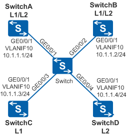
As shown in Figure 1, four switches on the broadcast network communicate using IS-IS. SwitchA and SwitchB are Level-1-2 devices, SwitchC is a Level-1 device, and SwitchD is a Level-2 device. SwitchA with high performance needs to be configured as a Level-2 DIS.
Configuration Roadmap
The configuration roadmap is as follows:
Configure IS-IS to enable network interconnectivity.
Configure the DIS priority of Switch A to 100 so that SwitchA can be elected as a Level-2 DIS.
Procedure
- Create VLANs and add corresponding interfaces to the VLANs.
# Configure SwitchA. The configurations of Switch, SwitchB, SwitchC, and SwitchD are similar to the configuration of SwitchA.
<HUAWEI> system-view
[HUAWEI] sysname SwitchA
[SwitchA] vlan batch 10
[SwitchA] interface gigabitethernet 0/0/1
[SwitchA-GigabitEthernet0/0/1] port link-type trunk
[SwitchA-GigabitEthernet0/0/1] port trunk allow-pass vlan 10
[SwitchA-GigabitEthernet0/0/1] quit
- Assign an IP address to each VLANIF interface.
# Configure SwitchA. The configurations of SwitchB, SwitchC, and SwitchD are similar to the configuration of SwitchA.
[SwitchA] interface vlanif 10
[SwitchA-Vlanif10] ip address 10.1.1.1 24
[SwitchA-Vlanif10] quit
- View the MAC address of the VLANIF 10 interface on each Switch.
# View the MAC address of the VLANIF 10 interface on SwitchA.
[SwitchA] display interface Vlanif 10
Vlanif10 current state : UP
Line protocol current state : UP
Last line protocol up time : 2014-12-02 18:02:15 UTC+08:00
Description:
Route Port,The Maximum Transmit Unit is 1500
Internet Address is 10.1.1.1/24
IP Sending Frames' Format is PKTFMT_ETHNT_2, Hardware address is 00e0-fc10-afec
Current system time: 2014-12-02 18:03:12+08:00
    Input bandwidth utilization  : --
    Output bandwidth utilization : --
# View the MAC address of the VLANIF 10 interface on SwitchB.
[SwitchB] display interface Vlanif 10
Vlanif10 current state : UP
Line protocol current state : UP
Last line protocol up time : 2014-12-02 18:01:15 UTC+08:00
Description:
Route Port,The Maximum Transmit Unit is 1500
Internet Address is 10.1.1.2/24
IP Sending Frames' Format is PKTFMT_ETHNT_2, Hardware address is 00e0-fccd-acdf
Current system time: 2014-12-02 18:02:12+08:00
    Input bandwidth utilization  : --
    Output bandwidth utilization : --
# View the MAC address of the VLANIF 10 interface on SwitchC.
[SwitchC] display interface Vlanif 10
Vlanif10 current state : UP
Line protocol current state : UP
Last line protocol up time : 2014-12-02 18:03:15 UTC+08:00
Description:
Route Port,The Maximum Transmit Unit is 1500
Internet Address is 10.1.1.3/24
IP Sending Frames' Format is PKTFMT_ETHNT_2, Hardware address is 00e0-fc50-25fe
Current system time: 2014-12-02 18:04:12+08:00
    Input bandwidth utilization  : --
    Output bandwidth utilization : --
# View the MAC address of the VLANIF 10 interface on SwitchD.
[SwitchD] display interface Vlanif 10 Vlanif10 current state : UP Line protocol current state : UP Last line protocol up time : 2014-12-02 18:07:15 UTC+08:00 Description: Route Port,The Maximum Transmit Unit is 1500 Internet Address is 10.1.1.4/24 IP Sending Frames' Format is PKTFMT_ETHNT_2, Hardware address is 00e0-fcfd-305c Current system time: 2014-12-02 18:08:12+08:00 Input bandwidth utilization : -- Output bandwidth utilization : -- - Configure basic IS-IS functions.
# Configure SwitchA.
[SwitchA] isis 1
[SwitchA-isis-1] network-entity 10.0000.0000.0001.00
[SwitchA-isis-1] quit
[SwitchA] interface vlanif 10
[SwitchA-Vlanif10] isis enable 1
[SwitchA-Vlanif10] quit
# Configure SwitchB.
[SwitchB] isis 1
[SwitchB-isis-1] network-entity 10.0000.0000.0002.00
[SwitchB-isis-1] quit
[SwitchB] interface vlanif 10
[SwitchB-Vlanif10] isis enable 1
[SwitchB-Vlanif10] quit
# Configure SwitchC.
[SwitchC] isis 1
[SwitchC-isis-1] network-entity 10.0000.0000.0003.00
[SwitchC-isis-1] is-level level-1
[SwitchC-isis-1] quit
[SwitchC] interface vlanif 10
[SwitchC-Vlanif10] isis enable 1
[SwitchC-Vlanif10] quit
# Configure SwitchD.
[SwitchD] isis 1
[SwitchD-isis-1] network-entity 10.0000.0000.0004.00
[SwitchD-isis-1] is-level level-2
[SwitchD-isis-1] quit
[SwitchD] interface vlanif 10
[SwitchD-Vlanif10] isis enable 1
[SwitchD-Vlanif10] quit
# View information about the IS-IS neighbors of SwitchA.
[SwitchA] display isis peer

                          Peer information for ISIS(1)

  System Id         Interface         Circuit Id        State HoldTime Type       PRI
-------------------------------------------------------------------------------
  0000.0000.0002    Vlanif10          0000.0000.0002.01  Up    9s       L1(L1L2)  64
  0000.0000.0003    Vlanif10          0000.0000.0002.01  Up    27s      L1        64
  0000.0000.0002    Vlanif10          0000.0000.0004.01  Up    28s      L2(L1L2)  64
  0000.0000.0004    Vlanif10          0000.0000.0004.01  Up    8s       L2        64

Total Peer(s): 4
# View information about the IS-IS interface of SwitchA.
[SwitchA] display isis interface

                       Interface information for ISIS(1)
                       ---------------------------------
 Interface       Id      IPV4.State          IPV6.State      MTU  Type  DIS
 Vlanif10        001      Up                    Down         1497 L1/L2 No/No
# View information about the IS-IS interface of SwitchB.
[SwitchB] display isis interface

                       Interface information for ISIS(1)
                       ---------------------------------
 Interface       Id      IPV4.State          IPV6.State      MTU  Type  DIS
 Vlanif10        001         Up                 Down         1497 L1/L2 Yes/No
# View information about the IS-IS interface of SwitchD.
[SwitchD] display isis interface

                       Interface information for ISIS(1)
                       ---------------------------------
 Interface       Id      IPV4.State          IPV6.State      MTU  Type  DIS
 Vlanif10        001         Up                 Down         1497 L1/L2 No/Yes

When the default DIS priority is used, the interface on SwitchB has the greatest MAC address among all the interfaces on the Level-1 Switches. Therefore, SwitchB is elected as the Level-1 DIS. The interface on SwitchD has the greatest MAC address among all the interfaces on the Level-2 Switches. Therefore, SwitchD is elected as the Level-2 DIS. The Level-1 pseudonode is 0000.0000.0002.01. The Level-2 pseudonode is 0000.0000.0004.01.
- Set the DIS priority of SwitchA.
[SwitchA] interface vlanif 10
[SwitchA-Vlanif10] isis dis-priority 100
[SwitchA-Vlanif10] quit
# View information about the IS-IS neighbors of SwitchA.
[SwitchA] display isis peer Peer information for ISIS(1) System Id Interface Circuit Id State HoldTime Type PRI ------------------------------------------------------------------------------- 0000.0000.0002 Vlanif10 0000.0000.0001.01 Up 21s L1(L1L2) 64 0000.0000.0003 Vlanif10 0000.0000.0001.01 Up 27s L1 64 0000.0000.0002 Vlanif10 0000.0000.0001.01 Up 28s L2(L1L2) 64 0000.0000.0004 Vlanif10 0000.0000.0001.01 Up 30s L2 64 Total Peer(s): 4 - Verify the configuration.
# View information about the IS-IS interface of SwitchA.
[SwitchA] display isis interface

                       Interface information for ISIS(1)
                       ---------------------------------
 Interface       Id      IPV4.State          IPV6.State      MTU   Type  DIS
 Vlanif10        001         Up                 Down         1497  L1/L2 Yes/Yes
As shown in the output information, after the DIS priority of the IS-IS interface is changed, SwitchA immediately becomes a Level-1 and Level-2 DIS and its pseudonode is 0000.0000.0001.01.
# View information about the IS-IS neighbors and IS-IS interfaces on SwitchB.
[SwitchB] display isis peer Peer information for ISIS(1) System Id Interface Circuit Id State HoldTime Type PRI ------------------------------------------------------------------------------- 0000.0000.0001 Vlanif10 0000.0000.0001.01 Up 7s L1(L1L2) 100 0000.0000.0003 Vlanif10 0000.0000.0001.01 Up 25s L1 64 0000.0000.0001 Vlanif10 0000.0000.0001.01 Up 7s L2(L1L2) 100 0000.0000.0004 Vlanif10 0000.0000.0001.01 Up 25s L2 64 Total Peer(s): 4[SwitchB] display isis interface Interface information for ISIS(1) --------------------------------- Interface Id IPV4.State IPV6.State MTU Type DIS Vlanif10 001 Up Down 1497 L1/L2 No/No
# View information about the IS-IS neighbors and IS-IS interfaces on SwitchD.
[SwitchD] display isis peer Peer information for ISIS(1) System Id Interface Circuit Id State HoldTime Type PRI ------------------------------------------------------------------------------- 0000.0000.0002 Vlanif10 0000.0000.0001.01 Up 28s L2 64 0000.0000.0001 Vlanif10 0000.0000.0001.01 Up 9s L2 100 Total Peer(s): 2[SwitchD] display isis interface Interface information for ISIS(1) --------------------------------- Interface Id IPV4.State IPV6.State MTU Type DIS Vlanif10 001 Up Down 1497 L1/L2 No/No
Configuration Files
Switch configuration file
#
sysname Switch
#
vlan batch 10
#
interface GigabitEthernet0/0/1
 port link-type trunk
 port trunk allow-pass vlan 10
#
interface GigabitEthernet0/0/2
 port link-type trunk
 port trunk allow-pass vlan 10
#
interface GigabitEthernet0/0/3
 port link-type trunk
 port trunk allow-pass vlan 10
#
interface GigabitEthernet0/0/4
 port link-type trunk
 port trunk allow-pass vlan 10
#
return
SwitchA configuration file
#
sysname SwitchA
#
vlan batch 10
#
isis 1
 network-entity 10.0000.0000.0001.00
#
interface Vlanif10
 ip address 10.1.1.1 255.255.255.0
 isis enable 1
 isis dis-priority 100
#
interface GigabitEthernet0/0/1
 port link-type trunk
 port trunk allow-pass vlan 10
#
return
SwitchB configuration file
#
sysname SwitchB
#
vlan batch 10
#
isis 1
 network-entity 10.0000.0000.0002.00
#
interface Vlanif10
 ip address 10.1.1.2 255.255.255.0
 isis enable 1
#
interface GigabitEthernet0/0/1
 port link-type trunk
 port trunk allow-pass vlan 10
#
return
SwitchC configuration file
#
sysname SwitchC
#
vlan batch 10
#
isis 1
 is-level level-1
 network-entity 10.0000.0000.0003.00
#
interface Vlanif10
 ip address 10.1.1.3 255.255.255.0
 isis enable 1
#
interface GigabitEthernet0/0/1
 port link-type trunk
 port trunk allow-pass vlan 10
#
return
SwitchD configuration file
#
sysname SwitchD
#
vlan batch 10
#
isis 1
 is-level level-2
 network-entity 10.0000.0000.0004.00
#
interface Vlanif10
 ip address 10.1.1.4 255.255.255.0
 isis enable 1
#
interface GigabitEthernet0/0/1
 port link-type trunk
 port trunk allow-pass vlan 10
#
return