Example for Configuring IS-IS Auto FRR (IP Protecting IP)
Networking Requirements
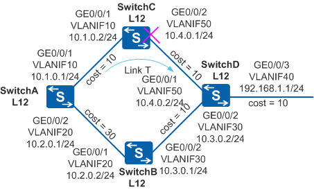
As shown in Figure 1, four routers (RouterA, RouterB, RouterC, and RouterD) communicate using IS-IS. Reliability of data forwarding from RouterA to RouterD needs to be improved so that uninterrupted traffic transmission is ensured when a fault occurs on the network.

In this scenario, ensure that all connected interfaces have STP disabled. If STP is enabled and VLANIF interfaces of switches are used to construct a Layer 3 ring network, an interface on the network will be blocked. As a result, Layer 3 services on the network cannot run normally.
Configuration Roadmap
The configuration roadmap is as follows:
Configure IP addresses for interfaces and enable IS-IS on each switch to ensure reachable routes between the switches.
Set a larger link cost (in compliance with the traffic protection inequality of IS-IS Auto FRR) on GigabitEthernet0/0/2 of SwitchA to ensure that Link T functions as the primary link to forward data from SwitchA to SwitchD.
Configure IS-IS Auto FRR on SwitchA to allow traffic to be fast switched to the backup link without waiting for route convergence when a fault occurs on Link T. This ensures uninterrupted traffic transmission.
Procedure
- Configure VLANs that interfaces belong to.
# Configure SwitchA. The configurations of SwitchB, SwitchC and SwitchD are similar to the configuration of SwitchA.
<HUAWEI> system-view
[HUAWEI] sysname SwitchA
[SwitchA] vlan batch 10 20
[SwitchA] interface gigabitethernet 0/0/1
[SwitchA-GigabitEthernet0/0/1] port link-type trunk
[SwitchA-GigabitEthernet0/0/1] port trunk allow-pass vlan 10
[SwitchA-GigabitEthernet0/0/1] quit
[SwitchA] interface gigabitethernet 0/0/2
[SwitchA-GigabitEthernet0/0/2] port link-type trunk
[SwitchA-GigabitEthernet0/0/2] port trunk allow-pass vlan 20
[SwitchA-GigabitEthernet0/0/2] quit
- Assign an IP address to each VLANIF interface.
# Configure SwitchA. The configurations of SwitchB, SwitchC and SwitchD are similar to the configuration of SwitchA.
[SwitchA] interface vlanif 10
[SwitchA-Vlanif10] ip address 10.1.0.1 24
[SwitchA-Vlanif10] quit
[SwitchA] interface vlanif 20
[SwitchA-Vlanif20] ip address 10.2.0.1 24
[SwitchA-Vlanif20] quit
- Configure basic IS-IS functions.
# Configure SwitchA.
[SwitchA] isis 1
[SwitchA-isis-1] is-level level-1-2
[SwitchA-isis-1] network-entity 10.0000.0000.0001.00
[SwitchA-isis-1] quit
[SwitchA] interface vlanif 10
[SwitchA-Vlanif10] isis enable 1
[SwitchA-Vlanif10] quit
[SwitchA] interface vlanif 20
[SwitchA-Vlanif20] isis enable 1
[SwitchA-Vlanif20] quit
# Configure SwitchB.
[SwitchB] isis 1
[SwitchB-isis-1] is-level level-1-2
[SwitchB-isis-1] network-entity 10.0000.0000.0002.00
[SwitchB-isis-1] quit
[SwitchB] interface vlanif 20
[SwitchB-Vlanif20] isis enable 1
[SwitchB-Vlanif20] quit
[SwitchB] interface vlanif 30
[SwitchB-Vlanif30] isis enable 1
[SwitchB-Vlanif30] quit
# Configure SwitchC.
[SwitchC] isis 1
[SwitchC-isis-1] is-level level-1-2
[SwitchC-isis-1] network-entity 10.0000.0000.0003.00
[SwitchC-isis-1] quit
[SwitchC] interface vlanif 10
[SwitchC-Vlanif10] isis enable 1
[SwitchC-Vlanif10] quit
[SwitchC] interface vlanif 50
[SwitchC-Vlanif50] isis enable 1
[SwitchC-Vlanif50] quit
# Configure SwitchD.
[SwitchD] isis 1
[SwitchD-isis-1] is-level level-1-2
[SwitchD-isis-1] network-entity 10.0000.0000.0004.00
[SwitchD-isis-1] quit
[SwitchD] interface vlanif 50
[SwitchD-Vlanif50] isis enable 1
[SwitchD-Vlanif50] quit
[SwitchD] interface vlanif 30
[SwitchD-Vlanif30] isis enable 1
[SwitchD-Vlanif30] quit
[SwitchD] interface vlanif 40
[SwitchD-Vlanif40] isis enable 1
[SwitchD-Vlanif40] quit
- Set the cost of Vlanif20 on SwitchA to 30, and then check
routing information.
# Configure the cost of Vlanif20 on SwitchA to 30.
[SwitchA] interface vlanif 20
[SwitchA-Vlanif20] isis cost 30
[SwitchA-Vlanif20] quit
# Check information about the link from SwitchA to SwitchD. Link T has a lower cost, and thereby IS-IS optimally selects Link T to send traffic that is forwarded by SwitchA.
[SwitchA] display isis route 192.168.1.1 verbose

                         Route information for ISIS(1)
                         -----------------------------

                        ISIS(1) Level-1 Forwarding Table
                        --------------------------------

 IPV4 Dest  : 192.168.1.0/24     Int. Cost : 30            Ext. Cost : NULL
 Admin Tag  : -                  Src Count : 1             Flags     : A/-/L/-
 Priority   : Low
 NextHop    :                    Interface :               ExitIndex :
    10.1.0.2                  Vlanif10                   0x00000003

     Flags: D-Direct, A-Added to URT, L-Advertised in LSPs, S-IGP Shortcut,
                               U-Up/Down Bit Set


                        ISIS(1) Level-2 Forwarding Table
                        --------------------------------

 IPV4 Dest  : 192.168.1.0/24     Int. Cost : 30            Ext. Cost : NULL
 Admin Tag  : -                  Src Count : 3             Flags     : -/-/-/-
 Priority   : Low

     Flags: D-Direct, A-Added to URT, L-Advertised in LSPs, S-IGP Shortcut,
                               U-Up/Down Bit Set
# Run the display fib 192.168.1.1 verbose command on SwitchA to check the forwarding entry from SwitchA to SwitchD.
[SwitchA] display fib 192.168.1.1 verbose

  Route Entry Count: 1
 Destination: 192.168.1.0         Mask     : 255.255.255.0
 Nexthop    : 10.1.0.2           OutIf    : Vlanif10
 LocalAddr  : 10.1.0.1            LocalMask: 0.0.0.0
 Flags      : DGU                 Age      : 26sec
 ATIndex    : 0                   Slot     : 0
 LspFwdFlag : 0                   LspToken : 0x0
 InLabel    : NULL                OriginAs : 0
 BGPNextHop : 0.0.0.0             PeerAs   : 0
 QosInfo    : 0x0                 OriginQos: 0x0
 NexthopBak : 0.0.0.0             OutIfBak : [No Intf]
 LspTokenBak: 0x0                 InLabelBak : NULL
 LspToken_ForInLabelBak     : 0x0
 EntryRefCount : 0
 VlanId : 0x0
 BgpKey : 0
 BgpKeyBak : 0
 LspType         : 0              Label_ForLspTokenBak   : 0
 MplsMtu         : 0              Gateway_ForLspTokenBak : 0.0.0.0
 NextToken       : 0x0            IfIndex_ForLspTokenBak : 0
 Label_NextToken : 0              Label : 0
 LspBfdState     : 0
As shown in the command output, the traffic from SwitchA to SwitchD is only forwarded through Link T.
- Enable IS-IS Auto FRR on SwitchA, and then check the routing
information.
# Enable IS-IS Auto FRR on SwitchA.
[SwitchA] isis
[SwitchA-isis-1] frr
[SwitchA-isis-1-frr] loop-free-alternate
# Check information about the link from SwitchA to SwitchD. You can find that IS-IS creates a backup link because IS-IS Auto FRR is enabled.
[SwitchA] display isis route 192.168.1.1 verbose

                         Route information for ISIS(1)
                         -----------------------------

                        ISIS(1) Level-1 Forwarding Table
                        --------------------------------

 IPV4 Dest  : 192.168.1.0/24     Int. Cost : 30            Ext. Cost : NULL
 Admin Tag  : -                  Src Count : 1             Flags     : A/-/L/-
 Priority   : Low
 NextHop    :                    Interface :               ExitIndex :
    10.1.0.2                           Vlanif10                   0x00000003
 (B)10.2.0.2                           Vlanif20                  0x00000004

     Flags: D-Direct, A-Added to URT, L-Advertised in LSPs, S-IGP Shortcut,
                               U-Up/Down Bit Set


                        ISIS(1) Level-2 Forwarding Table
                        --------------------------------

 IPV4 Dest  : 192.168.1.0/24     Int. Cost : 30            Ext. Cost : NULL
 Admin Tag  : -                  Src Count : 3             Flags     : -/-/-/-
 Priority   : Low

     Flags: D-Direct, A-Added to URT, L-Advertised in LSPs, S-IGP Shortcut,
                               U-Up/Down Bit Set
# Check the protection type for the traffic from SwitchA to SwitchD.
[SwitchA] display isis spf-tree systemid 0000.0000.0004 verbose

                         Shortest Path Tree for ISIS(1)
                         ------------------------------

                       ISIS(1) Level-1 Shortest Path Tree
                       ----------------------------------
 0000.0000.0004.00
   Distance            : 20
   Distance-URT        : 20
   Flags               : SPT/V6_Islt
   IPv4 Nexthops-URT   : 1
             (1) 10.1.0.2         IF:Vlanif10  NBR:0000.0000.0003.00
             (B) 10.2.0.2         IF:Vlanif20  NBR:0000.0000.0002.00
                                  TYPE:LOOP-FREE  PROTECT:LINK-NODE
   IPv4 Nexthops-MIGP  : 0
   IPv6 Nexthops       : 0
   Neighbors: 2 (Children:1 Parents:1 Others:0)
             (1)   0000.0000.0003.02
                     Cost  : 10
                     Flags : Parent

             (2)   0000.0000.0004.03
                     Cost  : 10
                     Flags : Child


                       ISIS(1) Level-2 Shortest Path Tree
                       ----------------------------------
 0000.0000.0004.00
   Distance            : 20
   Distance-URT        : 20
   Flags               : SPT/V6_Islt
   IPv4 Nexthops-URT   : 1
             (1) 10.1.0.2         IF:Vlanif10  NBR:0000.0000.0003.00
             (B) 10.2.0.2         IF:Vlanif20  NBR:0000.0000.0002.00
                                  TYPE:LOOP-FREE  PROTECT:LINK-NODE
   IPv4 Nexthops-MIGP  : 0
   IPv6 Nexthops       : 0
   Neighbors: 2 (Children:1 Parents:1 Others:0)
             (1)   0000.0000.0003.02
                     Cost  : 10
                     Flags : Parent

             (2)   0000.0000.0004.03
                     Cost  : 10
                     Flags : Child
As shown in the preceding command output, link-node dual protection is enabled from SwitchA to SwitchD.
# Run the display fib 192.168.1.1 verbose command on SwitchA to check the backup forwarding entry from SwitchA to SwitchD.
[SwitchA] display fib 192.168.1.1 verbose
  Route Entry Count: 1
 Destination: 192.168.1.0         Mask     : 255.255.255.0
 Nexthop    : 10.1.0.2            OutIf    : Vlanif10
 LocalAddr  : 10.1.0.1            LocalMask: 0.0.0.0
 Flags      : DGU                 Age      : 6sec
 ATIndex    : 0                   Slot     : 0
 LspFwdFlag : 0                   LspToken : 0x0
 InLabel    : NULL                OriginAs : 0
 BGPNextHop : 0.0.0.0             PeerAs   : 0
 QosInfo    : 0x0                 OriginQos: 0x0
 NexthopBak : 10.2.0.2            OutIfBak : Vlanif20
 LspTokenBak: 0x0                 InLabelBak : NULL
 LspToken_ForInLabelBak     : 0x0
 EntryRefCount : 0
 VlanId : 0x0
 BgpKey : 0
 BgpKeyBak : 0
 LspType         : 0              Label_ForLspTokenBak   : 0
 MplsMtu         : 0              Gateway_ForLspTokenBak : 0.0.0.0
 NextToken       : 0x0            IfIndex_ForLspTokenBak : 0
 Label_NextToken : 0              Label : 0
 LspBfdState     : 0
As shown in the command output, the master link from SwitchA to SwitchD is Link T, the relevant backup link follows the route with Vlanif20 as the outbound interface and 10.2.0.2 as the next hop.
- Verify the configuration.
# Run the shutdown command on Vlanif50 of SwitchC to make the link down.
[SwitchC] interface vlanif 50
[SwitchC-Vlanif50] shutdown
# Run the display fib 192.168.1.1 verbose command immediately on SwitchA to check information about the route from SwitchA to SwitchD.
[SwitchA] display fib 192.168.1.1 verbose
  Route Entry Count: 1
 Destination: 192.168.1.0         Mask     : 255.255.255.0
 Nexthop    : 10.2.0.2            OutIf    : Vlanif20
 LocalAddr  : 10.2.0.1            LocalMask: 0.0.0.0
 Flags      : DGU                 Age      : 124sec
 ATIndex    : 0                   Slot     : 0
 LspFwdFlag : 0                   LspToken : 0x0
 InLabel    : NULL                OriginAs : 0
 BGPNextHop : 0.0.0.0             PeerAs   : 0
 QosInfo    : 0x0                 OriginQos: 0x0
 NexthopBak : 0.0.0.0             OutIfBak : [No Intf]
 LspTokenBak: 0x0                 InLabelBak : NULL
 LspToken_ForInLabelBak     : 0x0
 EntryRefCount : 0
 VlanId : 0x0
 BgpKey : 0
 BgpKeyBak : 0
 LspType         : 0              Label_ForLspTokenBak   : 0
 MplsMtu         : 0              Gateway_ForLspTokenBak : 0.0.0.0
 NextToken       : 0x0              IfIndex_ForLspTokenBak : 0
 Label_NextToken : 0              Label : 0
 LspBfdState     : 0
As shown in the command output, the traffic forwarded by the SwitchA is switched to the backup link, with Vlanif20 as the outbound interface and 10.2.0.2 as the next hop.
If a fault occurs on the network, IS-IS Auto FRR ensures the fast switchover of the traffic to the backup link before the network convergence, and consequently protects traffic.
Configuration Files
Configuration file of SwitchA
#
sysname SwitchA
#
vlan batch 10 20
#
isis 1
 network-entity 10.0000.0000.0001.00
 frr
  loop-free-alternate level-1
  loop-free-alternate level-2
#
interface Vlanif10
 ip address 10.1.0.1 255.255.255.0
 isis enable 1
#
interface Vlanif20
 ip address 10.2.0.1 255.255.255.0
 isis enable 1
 isis cost 30
#
interface GigabitEthernet0/0/1
 port link-type trunk
 port trunk allow-pass vlan 10
#
interface GigabitEthernet0/0/2
 port link-type trunk
 port trunk allow-pass vlan 20
#
return
Configuration file of SwitchB
#
sysname SwitchB
#
vlan batch 20 30
#
isis 1
 network-entity 10.0000.0000.0002.00
#
interface Vlanif20
 ip address 10.2.0.2 255.255.255.0
 isis enable 1
#
interface Vlanif30
 ip address 10.3.0.1 255.255.255.0
 isis enable 1
#
interface GigabitEthernet0/0/1
 port link-type trunk
 port trunk allow-pass vlan 20
#
interface GigabitEthernet0/0/2
 port link-type trunk
 port trunk allow-pass vlan 30
#
return
Configuration file of SwitchC
#
sysname SwitchC
#
vlan batch 10 50
#
isis 1
 network-entity 10.0000.0000.0003.00
#
interface Vlanif10
 ip address 10.1.0.2 255.255.255.0
 isis enable 1
#
interface Vlanif50
 ip address 10.4.0.1 255.255.255.0
 isis enable 1
#
interface GigabitEthernet0/0/1
 port link-type trunk
 port trunk allow-pass vlan 10
#
interface GigabitEthernet0/0/2
 port link-type trunk
 port trunk allow-pass vlan 50
#
return
Configuration file of SwitchD
#
sysname SwitchD
#
vlan batch 30 40 50
#
isis 1
 network-entity 10.0000.0000.0004.00
#
interface Vlanif50
 ip address 10.4.0.2 255.255.255.0
 isis enable 1
#
interface Vlanif30
 ip address 10.3.0.2 255.255.255.0
 isis enable 1
#
interface Vlanif40
 ip address 192.168.1.1 255.255.255.0
 isis enable 1
#
interface GigabitEthernet0/0/1
 port link-type trunk
 port trunk allow-pass vlan 50
#
interface GigabitEthernet0/0/2
 port link-type trunk
 port trunk allow-pass vlan 30
#
interface GigabitEthernet0/0/3
 port link-type trunk
 port trunk allow-pass vlan 40
#
return