Example for Configuring Static BFD for IS-IS
Networking Requirements
As shown in Figure 1, three routers are interconnected using IS-IS, and SwitchA and SwitchB communicate with each other through a Layer 2 switch. When the link between SwitchA and SwitchB is faulty, the two routers need to rapidly respond to the fault and reestablish a neighbor relationship.
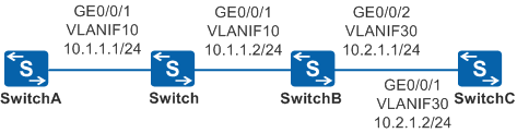

BFD for IS-IS cannot be used to detect the multi-hop link between SwitchA and SwitchC, because the IS-IS neighbor relationship cannot be established between SwitchA and SwitchC.
Configuration Roadmap
The configuration roadmap is as follows:
Configure IP addresses for interfaces and enable IS-IS on each router to ensure reachable routes between the routers.
Enable static BFD for IS-IS on SwitchA and SwitchB so that routers can rapidly detect link faults.
Procedure
- Configure VLANs that each interface belongs to.
# Configure SwitchA. The configurations of Switch, SwitchB and SwitchC are similar to the configuration of SwitchA.
<HUAWEI> system-view
[HUAWEI] sysname SwitchA
[SwitchA] vlan batch 10
[SwitchA] interface gigabitethernet 0/0/1
[SwitchA-GigabitEthernet0/0/1] port link-type trunk
[SwitchA-GigabitEthernet0/0/1] port trunk allow-pass vlan 10
[SwitchA-GigabitEthernet0/0/1] quit
- Assign the IP addresses for VLANIF interfaces.
# Configure SwitchA. The configurations of SwitchB and SwitchC are similar to the configuration of SwitchA.
[SwitchA] interface vlanif 10
[SwitchA-Vlanif10] ip address 10.1.1.1 24
[SwitchA-Vlanif10] quit
- Configure basic IS-IS functions.
# Configure SwitchA.
[SwitchA] isis 1
[SwitchA-isis-1] is-level level-2
[SwitchA-isis-1] network-entity aa.1111.1111.1111.00
[SwitchA-isis-1] quit
[SwitchA] interface vlanif 10
[SwitchA-Vlanif10] isis enable 1
[SwitchA-Vlanif10] quit
# Configure SwitchB.
[SwitchB] isis 1
[SwitchB-isis-1] is-level level-2
[SwitchB-isis-1] network-entity aa.2222.2222.2222.00
[SwitchB-isis-1] quit
[SwitchB] interface vlanif 10
[SwitchB-Vlanif10] isis enable 1
[SwitchB-Vlanif10] quit
[SwitchB] interface vlanif 30
[SwitchB-Vlanif30] isis enable 1
[SwitchB-Vlanif30] quit
# Configure SwitchC.
[SwitchC] isis 1
[SwitchC-isis-1] is-level level-2
[SwitchC-isis-1] network-entity aa.3333.3333.3333.00
[SwitchC-isis-1] quit
[SwitchC] interface vlanif 30
[SwitchC-Vlanif30] isis enable 1
[SwitchC-Vlanif30] quit
# After the preceding configurations, you can see that the neighbor relationship is established between SwitchA and SwitchB.
[SwitchA] display isis peer

                          Peer information for ISIS(1)

  System Id     Interface          Circuit Id       State HoldTime Type     PRI
-------------------------------------------------------------------------------
2222.2222.2222 Vlanif10          1111.1111.1111.01 Up   23s      L2       64

Total Peer(s): 1
The IS-IS routing table of SwitchA contains the routes to SwitchB and SwitchC.
[SwitchA] display isis route

                         Route information for ISIS(1)
                         -----------------------------

                        ISIS(1) Level-2 Forwarding Table
                        --------------------------------

 IPV4 Destination     IntCost    ExtCost ExitInterface   NextHop         Flags
-------------------------------------------------------------------------------
 10.2.1.0/24         20        NULL    Vlanif10         10.1.1.2     A/-/L/-
 10.1.1.0/24         10        NULL    Vlanif10         Direct       D/-/L/-
     Flags: D-Direct, A-Added to URT, L-Advertised in LSPs, S-IGP Shortcut,
                               U-Up/Down Bit Set
- Configure BFD.
# Enable BFD on SwitchA and configure a BFD session.
[SwitchA] bfd
[SwitchA-bfd] quit
[SwitchA] bfd atob bind peer-ip 10.1.1.2 interface vlanif 10
[SwitchA-bfd-session-atob] discriminator local 1
[SwitchA-bfd-session-atob] discriminator remote 2
[SwitchA-bfd-session-atob] commit
[SwitchA-bfd-session-atob] quit
# Enable BFD on SwitchB and configure a BFD session.
[SwitchB] bfd
[SwitchB-bfd] quit
[SwitchB] bfd btoa bind peer-ip 10.1.1.1 interface vlanif 10
[SwitchB-bfd-session-btoa] discriminator local 2
[SwitchB-bfd-session-btoa] discriminator remote 1
[SwitchB-bfd-session-btoa] commit
[SwitchB-bfd-session-btoa] quit
After the preceding configurations, run the display bfd session command on SwitchA or SwitchB, and you can see that the status of the BFD session is Up.
The following uses the display on SwitchA as an example.
[SwitchA] display bfd session all -------------------------------------------------------------------------------- Local Remote PeerIpAddr State Type InterfaceName -------------------------------------------------------------------------------- 1 2 10.1.1.2 Up S_IP_IF Vlanif10 -------------------------------------------------------------------------------- Total UP/DOWN Session Number : 1/0 - Enable IS-IS fast detection.
# Configure SwitchA.
[SwitchA] interface vlanif 10
[SwitchA-Vlanif10] isis bfd static
[SwitchA-Vlanif10] quit
# Configure SwitchB.
[SwitchB] interface vlanif 10
[SwitchB-Vlanif10] isis bfd static
[SwitchB-Vlanif10] quit
- Verify the configuration.
# Enable log information display on SwitchA.
[SwitchA] info-center source bfd channel 1 log level debugging state on
[SwitchA] quit
<SwitchA> debugging isis circuit-information
<SwitchA> terminal debugging
<SwitchA> terminal logging
<SwitchA> terminal monitor
# Run the shutdown command on GigabitEthernet0/0/1 on SwitchB to simulate a link fault.
[SwitchB]interface gigabitethernet 0/0/1
[SwitchB-GigabitEthernet0/0/1] shutdown
# On SwitchA, you can view the following log and debugging information, which indicates that IS-IS deletes the neighbor relationship with SwitchB after being notified by BFD of the fault.
May 19 2013 09:34:49+08:00 SwitchB %%01ISIS/4/PEER_DOWN_BFDDOWN(l)[2]:ISIS 1 ne
ighbor 2222.2222.2222 was Down on interface Vlanif2710 because the BFD node was d
own.
 The Hello packet was received at 09:29:39 last time; the maximum interval for se
 nding Hello packets was 8944; the local router sent 392 Hello packets and receiv
 ed 2 packets; the type of the Hello packet was Lan Level-2.
Run the display isis route command or the display isis peer command on SwitchA, and you can see that no information is displayed. This indicates that the IS-IS neighbor relationship between SwitchA and SwitchB is deleted.
# After the configuration is checked, disable debugging on SwitchA.
<SwitchA> undo debugging isis circuit-information
<SwitchA> undo terminal debugging
<SwitchA> undo terminal logging
<SwitchA> undo terminal monitor
Configuration Files
Switch configuration file
#
sysname Switch
#
vlan batch 10
#
interface GigabitEthernet0/0/1
 port link-type trunk
 port trunk allow-pass vlan 10
#
interface GigabitEthernet0/0/2
 port link-type trunk
 port trunk allow-pass vlan 10
#
return
SwitchA configuration file
#
sysname SwitchA
#
info-center source BFD channel 1 log level debugging
#
vlan batch 10
#
bfd
#
isis 1
 is-level level-2
 network-entity aa.1111.1111.1111.00
#
interface Vlanif10
 ip address 10.1.1.1 255.255.255.0
 isis enable 1
 isis bfd static
#
interface GigabitEthernet0/0/1
 port link-type trunk
 port trunk allow-pass vlan 10
#
bfd atob bind peer-ip 10.1.1.2 interface Vlanif10
 discriminator local 1
 discriminator remote 2
 commit
#
return
SwitchB configuration file
#
sysname SwitchB
#
vlan batch 10 30
#
bfd
#
isis 1
 is-level level-2
 network-entity aa.2222.2222.2222.00
#
interface Vlanif10
 ip address 10.1.1.2 255.255.255.0
 isis enable 1
 isis bfd static
#
interface Vlanif30
 ip address 10.2.1.1 255.255.255.0
 isis enable 1
#
interface GigabitEthernet0/0/1
 port link-type trunk
 port trunk allow-pass vlan 10
#
interface GigabitEthernet0/0/2
 port link-type trunk
 port trunk allow-pass vlan 30
#
bfd btoa bind peer-ip 10.1.1.1 interface Vlanif10
 discriminator local 2
 discriminator remote 1
 commit
#
return
SwitchC configuration file
#
sysname SwitchC
#
vlan batch 30
#
isis 1
 is-level level-2
 network-entity aa.3333.3333.3333.00
#
interface Vlanif30
 ip address 10.2.1.2 255.255.255.0
 isis enable 1
#
interface GigabitEthernet0/0/1
 port link-type trunk
 port trunk allow-pass vlan 30
#
return