Adding and Removing a Stack Member
Adding a Stack Member

A switch can be added to a stack whether it is powered on or off. This section only describes how a member switch joins a stack after being powered off. For details on how a member switch joins a stack after being powered on, see Stack Merging.
It is not recommended to add a member switch to a stack while the power is on.
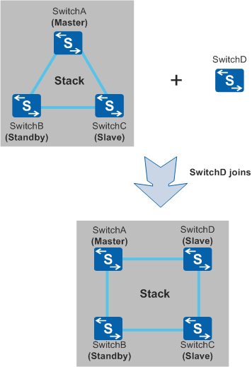
The new switch is connected to the stack, is powered on, and starts. It is elected as a slave switch, while the roles of other stack members remain unchanged.
The master switch updates stack topology information, synchronizes the information to the other member switches, and assigns a stack ID to the new stack member (if it has no stack ID configured or the configured stack ID conflicts with that of another stack member).
The new stack member updates its stack ID, synchronizes its configuration file and system software with the master switch, and then runs stably.
To add a new switch to a stack, perform the following operations:
Examine the physical connections between the existing stack members and determine where to connect the new stack member.
- If the stack has a chain topology, add the new switch to either end of the chain to minimize the impact on running services.
- If the stack has a ring topology, tear down a physical link to change the ring topology to a chain topology, and add the new switch to either end of the chain. Then connect the switches at both ends to form a ring if required.
Complete the stack configuration.
- If the member switches are connected through service ports, configure the connected service ports on the new member switch as stack member ports of a logical stack port. If the stack has a chain topology, perform this configuration also at one or both ends of the chain.
- If the member switches are connected through stack cards, enable the stacking function on the new member switch.
- To facilitate device management, configure a stack ID for the new member switch. If no stack ID is configured for it, the master switch will assign a stack ID to it.
Power off the new member switch, connect it to the stack through stack cables, and power it on.
Repeat steps 1 through 3 to add more switches to the stack.
Save the configuration.
Removing a Stack Member
- If the master switch leaves the stack, the standby switch becomes the new master switch. It recalculates topology information, synchronizes updated topology information to the other member switches, and selects a new standby switch. The stack enters the running state.
- If the standby switch leaves the stack, the master switch selects a new standby switch, recalculates topology information, and synchronizes updated topology information to the other member switches. The stack enters the running state.
- If a slave switch leaves the stack, the master switch recalculates topology information and synchronizes updated topology information to the other member switches. The stack enters the running state.
- In a ring topology, after removing the switch, use a stack cable to connect the two ports that were connected to this removed member switch to ensure network reliability.
- In a chain topology, removing an intermediate switch will cause the stack to split. Avoid removing an intermediate switch if it will have a significant impact on services.