Example for Adding a Member Switch to a Stack (Service Port Connection Using Dedicated Stack Cables)
Networking Requirements
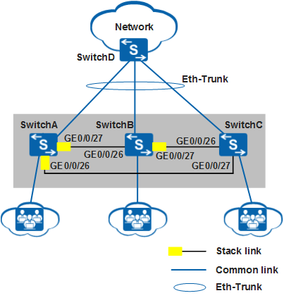
In Figure 1, SwitchA, SwitchB, and SwitchC set up a stack using dedicated stack cables to provide access service to users. The stack connects to SwitchD through an inter-chassis Eth-Trunk. SwitchA, SwitchB, and SwitchC are the master, standby, and slave switches respectively, with stack IDs of 0, 1, and 2 respectively. As the number of users increases, the current stack cannot provide sufficient ports for user access.
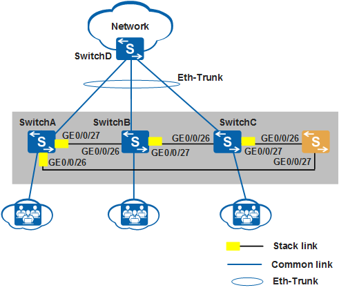
SwitchE needs to be added to the stack to increase the number of ports. Figure 2 shows the topology of the new stack.
This example describes how to use S5720-LI switches to set up a stack.
Configuration Roadmap
Analyze physical connections between original stack member switches to determine where to add the new member switch.
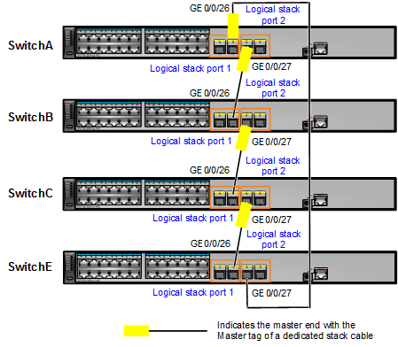
Power off SwitchE. Connect stack member ports using dedicated stack cables according to Figure 3 and then power on the switches.

Physical member ports of logical stack port stack-port n/1 on one switch can only be connected to the ports of stack-port m/2 on a neighboring switch.
Add the uplink port of SwitchE to the inter-chassis Eth-Trunk.
Procedure
- Determine the location for the new member switch.
# The stack in this example has a ring topology. To add the new member switch to the stack, tear down the link between SwitchA and SwitchC to change the stack topology to a chain topology, and then connect SwitchE to SwitchA and SwitchC.
- Power off SwitchE, use dedicated stack cables to connect GE0/0/27 and GE0/0/26 on SwitchE to corresponding ports on SwitchA and SwitchC according to Figure 3, and then power on SwitchE.
- Check basic stack information.
The command output shows that SwitchA, SwitchB, and SwitchC retain their roles and SwitchE becomes a slave switch and is automatically assigned a stack ID 3.
[SwitchA] display stack
Stack mode: Service-port
Stack topology type : Ring
Stack system MAC: 0018-82d2-2e85
MAC switch delay time: 10 min
Stack reserved vlan : 4093
Slot of the active management port: --
Slot     Role        Mac address      Priority   Device type
-------------------------------------------------------------
    0     Master      0018-82d2-2e85   100        S5720-28P-LI-AC
    1     Standby     0018-82c6-1f44   100        S5720-28P-LI-AC
    2     Slave       0018-82c6-1f4c   100        S5720-28P-LI-AC
    3     Slave       0018-82c6-1f4a   100        S5720-28P-LI-AC
- Add the uplink port of SwitchE to the inter-chassis Eth-Trunk.
For details about the configuration, see Example for Configuring Stack Eth-Trunks.