Example for Adding a Member Switch to a Stack (Service Port Connection Using Ordinary Stack Cables)
Networking Requirements
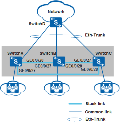
As shown in Figure 1, SwitchA, SwitchB, and SwitchC set up a stack to support user access and connect to an upstream device SwitchD through an Eth-Trunk. SwitchA, SwitchB, and SwitchC are the master, standby, and slave switches respectively, with stack IDs of 0, 1, and 2 and stack priorities of 200, 100, and 100. As an increasing number of users need to connect to the network, the current stack cannot provide a sufficient number of ports.
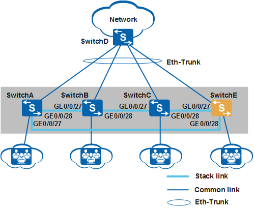
SwitchE is added to the stack as shown in Figure 2 to increase the number of ports available for user access.
The S5720-LI series switches are used on the network.
Configuration Roadmap
Examine the physical connections of the stack to determine a location for the new member switch.
Perform software configurations for service port stacking on SwitchE: configure logical stack ports and add physical member ports to the corresponding logical stack ports, and configure stack IDs.
Power off SwitchE, connect physical member ports using SFP+ stack cables according to Figure 2, and then power on SwitchE.

Physical member ports of logical stack port stack-port n/1 on one switch can only be connected to the ports of stack-port m/2 on a neighboring switch.
Add the uplink port of SwitchE to the inter-device Eth-Trunk.
Procedure
- Determine a location for the new member switch.
# The stack in this example has a ring topology. Break the ring topology into a chain topology and add the new member switch to either end of the chain. Disconnect the link between SwitchA and SwitchC to break the ring.
If the member switches are running a software version earlier than V200R001, break the ring on the link between the master switch and standby switch. Otherwise, reelection will occur which will cause unnecessary role changes.
- Configure software for service port stacking.
# Configure the service ports GigabitEthernet0/0/27 and GigabitEthernet0/0/28 on SwitchE as physical member ports and add them to the corresponding logical stack ports.
The physical member ports GigabitEthernet0/0/27 and GigabitEthernet0/0/28 on SwitchA, SwitchB, and SwitchC are added to the logical stack ports stack-port n/1 and stack-port n/2 respectively.
<HUAWEI> system-view
[HUAWEI] sysname SwitchE
[SwitchE] interface stack-port 0/1
[SwitchE-stack-port0/1] port interface gigabitethernet 0/0/27 enable
Warning: Enabling stack function may cause configuration loss on the interface. Continue? [Y/N]:y
Info: This operation may take a few seconds. Please wait.
[SwitchE-stack-port0/1] quit
[SwitchE] interface stack-port 0/2
[SwitchE-stack-port0/2] port interface gigabitethernet 0/0/28 enable
Warning: Enabling stack function may cause configuration loss on the interface. Continue? [Y/N]:y
Info: This operation may take a few seconds. Please wait.
[SwitchE-stack-port0/2] quit
# Set the stack ID of SwitchE to 3.
[SwitchE] stack slot 0 renumber 3 Warning: All the configurations related to the slot ID will be lost after the slot ID is modified. Please do not frequently modify slot ID because it will make the stack split. Continue? [Y/N]:y Info: Stack configuration has been changed, and the device needs to restart to make the configuration effective. - Power off SwitchE, connect physical member ports on SwitchE to corresponding physical member ports on SwitchA and SwitchC according to Figure 2, and then power on SwitchE.
It is recommended that you run the save command to save the configurations before you power off SwitchE.
- Check basic stack information. The command output shows that the roles of member switches in the original stack remain unchanged and SwitchE has been elected as a slave switch.
<SwitchA> display stack
Stack mode: Service-port
Stack topology type : Ring
Stack system MAC: 0018-82d2-2e85
MAC switch delay time: 10 min
Stack reserved vlan : 4093
Slot of the active management port: --
Slot     Role        Mac address      Priority   Device type
-------------------------------------------------------------
    0     Master      0018-82d2-2e85   200        S5720-28P-LI-AC
    1     Standby     0018-82c6-1f44   100        S5720-28P-LI-AC
    2     Slave       0018-82c6-1f4c   100        S5720-28P-LI-AC
    3     Slave       0018-82c6-1f4a   100        S5720-28P-LI-AC
- Add the uplink port of SwitchE to the inter-device Eth-Trunk.
Configure an inter-device Eth-Trunk for the uplink port of SwitchE. For the detailed configuration process, see Example for Configuring Stack Eth-Trunks.