Example for Configuring IP+VPN Hybrid FRR
Networking Requirements
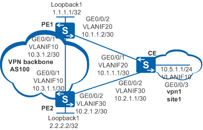
As shown in Figure 1, a CE is dual-homed to PE1 and PE2. The customer requires that when the direct link between CE and PE1 fails, the route can be quickly switched to the link PE1-PE2-CE to ensure rapid switching of VPN service traffic, thereby minimizing the impact of the link failure on VPN services.

In this scenario, to avoid loops, ensure that all connected interfaces have STP disabled and connected interfaces are removed from VLAN 1. If STP is enabled and VLANIF interfaces of switches are used to construct a Layer 3 ring network, an interface on the network will be blocked. As a result, Layer 3 services on the network cannot run normally.
Configuration Roadmap
The configuration roadmap is as follows:
Configure OSPF on the MPLS backbone network (PE1 and PE2) to enable interworking on the backbone network.
Enable basic MPLS capabilities and MPLS LDP to set up LDP LSPs on the MPLS backbone network.
Configure a VPN instance on PE1 and PE2, and bind the CE-side interfaces to the VPN instance to connect the CE to PE1 and PE2.
Establish a BGP VPNv4 peer relationship between PE1 and PE2.
Configure a hybrid FRR policy on PE1 and PE2, specify the backup next hop in the policy, and enable IP FRR.
Procedure
- Create VLANs, add related interfaces to the VLANs, and assign IP addresses to VLANIF and loopback interfaces.
# Configure PE1. The configurations of PE2 and CE are similar to the configurations of PE1. For details, see the configuration files.
<HUAWEI> system-view
[HUAWEI] sysname PE1
[PE1] interface loopback 1
[PE1-LoopBack1] ip address 1.1.1.1 32
[PE1-LoopBack1] quit
[PE1] vlan batch 10 20
[PE1] interface gigabitethernet 0/0/1
[PE1-GigabitEthernet0/0/1] port link-type trunk
[PE1-GigabitEthernet0/0/1] port trunk allow-pass vlan 10
[PE1-GigabitEthernet0/0/1] quit
[PE1] interface gigabitethernet 0/0/2
[PE1-GigabitEthernet0/0/2] port link-type trunk
[PE1-GigabitEthernet0/0/2] port trunk allow-pass vlan 20
[PE1-GigabitEthernet0/0/2] quit
[PE1] interface vlanif 10
[PE1-Vlanif10] ip address 10.3.1.2 30
[PE1-Vlanif10] quit
- Configure OSPF on the MPLS backbone network to enable interworking between the PE devices.
# Configure PE1. The configuration of PE2 is similar to the configuration of PE1. For details, see the configuration files.
[PE1] ospf
[PE1-ospf-1] area 0
[PE1-ospf-1-area-0.0.0.0] network 10.3.1.0 0.0.0.3
[PE1-ospf-1-area-0.0.0.0] network 1.1.1.1 0.0.0.0
[PE1-ospf-1-area-0.0.0.0] quit
[PE1-ospf-1] quit
- Enable basic MPLS capabilities and MPLS LDP on the PE devices to set up LDP LSPs on the MPLS backbone network.
# Configure PE1.
[PE1] mpls lsr-id 1.1.1.1
[PE1] mpls
[PE1-mpls] quit
[PE1] mpls ldp
[PE1-mpls-ldp] quit
[PE1] interface vlanif 10
[PE1-Vlanif10] mpls
[PE1-Vlanif10] mpls ldp
[PE1-Vlanif10] quit
# Configure PE2.
[PE2] mpls lsr-id 2.2.2.2
[PE2] mpls
[PE2-mpls] quit
[PE2] mpls ldp
[PE2-mpls-ldp] quit
[PE2] interface vlanif 10
[PE2-Vlanif10] mpls
[PE2-Vlanif10] mpls ldp
[PE2-Vlanif10] quit
After the configuration is complete, an LDP peer relationship is established between PE1 and PE2. Run the display mpls ldp session command on the PE devices. The command output shows that the Status is Operational. Run the display mpls ldp lsp command to view information about the established LDP LSPs. The display on PE1 is used as an example:
[PE1] display mpls ldp lsp LDP LSP Information ------------------------------------------------------------------------------- Flag after Out IF: (I) - LSP Is Only Iterated by RLFA ------------------------------------------------------------------------------- DestAddress/Mask In/OutLabel UpstreamPeer NextHop OutInterface ------------------------------------------------------------------------------- 1.1.1.1/32 3/NULL 2.2.2.2 127.0.0.1 InLoop0 *1.1.1.1/32 Liberal/1024 DS/2.2.2.2 2.2.2.2/32 NULL/3 - 10.3.1.1 Vlanif10 2.2.2.2/32 1024/3 2.2.2.2 10.3.1.1 Vlanif10 ------------------------------------------------------------------------------- TOTAL: 3 Normal LSP(s) Found. TOTAL: 1 Liberal LSP(s) Found. TOTAL: 0 Frr LSP(s) Found. A '*' before an LSP means the LSP is not established A '*' before a Label means the USCB or DSCB is stale A '*' before a UpstreamPeer means the session is stale A '*' before a DS means the session is stale A '*' before a NextHop means the LSP is FRR LSP - Configure a VPN instance on the PE devices and bind the CE-side interfaces to the VPN instance to connect the CE to the PE devices.
# Configure PE1.
[PE1] ip vpn-instance vpn1
[PE1-vpn-instance-vpn1] ipv4-family
[PE1-vpn-instance-vpn1-af-ipv4] route-distinguisher 100:1
[PE1-vpn-instance-vpn1-af-ipv4] vpn-target 111:1
[PE1-vpn-instance-vpn1-af-ipv4] quit
[PE1-vpn-instance-vpn1] quit
[PE1] interface vlanif 20
[PE1-Vlanif20] ip binding vpn-instance vpn1
[PE1-Vlanif20] ip address 10.1.1.2 30
[PE1-Vlanif20] quit
# Configure PE2.
[PE2] ip vpn-instance vpn1
[PE2-vpn-instance-vpn1] ipv4-family
[PE2-vpn-instance-vpn1-af-ipv4] route-distinguisher 100:2
[PE2-vpn-instance-vpn1-af-ipv4] vpn-target 111:1
[PE2-vpn-instance-vpn1-af-ipv4] quit
[PE2-vpn-instance-vpn1] quit
[PE2] interface vlanif 30
[PE2-Vlanif30] ip binding vpn-instance vpn1
[PE2-Vlanif30] ip address 10.2.1.2 30
[PE2-Vlanif30] quit
- Configure static routes between the CE and the PE devices. Import direct VPN routes and static routes on PE1 and PE2.
When configuring hybrid FRR, you must specify outbound interfaces in the static routes from the PE devices to the CE.
# Configure PE1.
[PE1] ip route-static vpn-instance vpn1 10.5.1.0 24 vlanif20 10.1.1.1
[PE1] bgp 100
[PE1-bgp] ipv4-family vpn-instance vpn1
[PE1-bgp-vpn1] import-route direct
[PE1-bgp-vpn1] import-route static
[PE1-bgp-vpn1] quit
[PE1-bgp] quit
# Configure PE2.
[PE2] ip route-static vpn-instance vpn1 10.5.1.0 24 vlanif30 10.2.1.1
[PE2] bgp 100
[PE2-bgp] ipv4-family vpn-instance vpn1
[PE2-bgp-vpn1] import-route direct
[PE2-bgp-vpn1] import-route static
[PE2-bgp-vpn1] quit
[PE2-bgp] quit
# Configure the CE.
[CE] ip route-static 0.0.0.0 0.0.0.0 10.1.1.2 preference 60
[CE] ip route-static 0.0.0.0 0.0.0.0 10.2.1.2 preference 100
- Set up a BGP VPNv4 peer relationship between PE1 and PE2.
# Configure PE1.
[PE1] bgp 100
[PE1-bgp] peer 2.2.2.2 as-number 100
[PE1-bgp] peer 2.2.2.2 connect-interface loopback 1
[PE1-bgp] ipv4-family vpnv4
[PE1-bgp-af-vpnv4] peer 2.2.2.2 enable
[PE1-bgp-af-vpnv4] quit
[PE1-bgp] quit
# Configure PE2.
[PE2] bgp 100
[PE2-bgp] peer 1.1.1.1 as-number 100
[PE2-bgp] peer 1.1.1.1 connect-interface loopback 1
[PE2-bgp] ipv4-family vpnv4
[PE2-bgp-af-vpnv4] peer 1.1.1.1 enable
[PE2-bgp-af-vpnv4] quit
[PE2-bgp] quit
After the configuration is complete, run the display bgp vpnv4 all peer command on PE1 and PE2. The command output shows that a BGP VPNv4 peer relationship has been set up and it is in the Established state.
- Configure a hybrid FRR routing policy.
[PE1] ip ip-prefix frr1 permit 10.1.1.1 32
[PE1] route-policy ip_vpn_frr_rp permit node 10
[PE1-route-policy] if-match ip next-hop ip-prefix frr1
[PE1-route-policy] apply backup-nexthop 2.2.2.2
[PE1-route-policy] quit
- Enable IP FRR.
[PE1] ip vpn-instance vpn1
[PE1-vpn-instance-vpn1] ipv4-family
[PE1-vpn-instance-vpn1-af-ipv4] ip frr route-policy ip_vpn_frr_rp
[PE1-vpn-instance-vpn1-af-ipv4] quit
[PE1-vpn-instance-vpn1] quit
# Run the display ip routing-table vpn-instance command to check the routing entries of the VPN instance. The fields in boldface indicate the backup next hop, backup label, and backup tunnel ID. The command output shows that the hybrid FRR entry has been generated.
[PE1] display ip routing-table vpn-instance vpn1 10.5.1.0 verbose
Route Flags: R - relay, D - download to fib, T - to vpn-instance
------------------------------------------------------------------------------
Routing Table : vpn1
Summary Count : 2

Destination: 10.5.1.0/24
     Protocol: Static          Process ID: 0
   Preference: 60                    Cost: 0
      NextHop: 10.1.1.1         Neighbour: 0.0.0.0
        State: Active Adv             Age: 00h01m33s
          Tag: 0                 Priority: medium
        Label: NULL               QoSInfo: 0x0
   IndirectID: 0x0
 RelayNextHop: 0.0.0.0          Interface: Vlanif20
     TunnelID: 0x0                  Flags:  D
    BkNextHop: 2.2.2.2        BkInterface: Vlanif10
      BkLabel: 75776          SecTunnelID: 0x0
 BkPETunnelID: 0x200800b  BkPESecTunnelID: 0x0
 BkIndirectID: 0x0

Destination: 10.5.1.0/24
     Protocol: IBGP             Process ID: 0
   Preference: 255                    Cost: 0
      NextHop: 2.2.2.2           Neighbour: 2.2.2.2
       State: Inactive Adv Relied     Age: 00h01m33s
         Tag: 0                  Priority: low
       Label: 1025                QoSInfo: 0x0
   IndirectID: 0x6
 RelayNextHop: 10.3.1.1          Interface: Vlanif10
     TunnelID: 0x48000007            Flags: R
When the link between PE1 and the CE fails, the static routes on the link become invalid. Then traffic is quickly switched to the backup link based on the FRR entry.
After IP FRR is disabled, traffic is switched based on route convergence. The switching speed is slower than switching based on IP FRR.
Configuration Files
PE1 configuration file
#
sysname PE1
#
vlan batch 10 20
#
ip vpn-instance vpn1
 ipv4-family
  route-distinguisher 100:1
  ip frr route-policy ip_vpn_frr_rp
  vpn-target 111:1 export-extcommunity
  vpn-target 111:1 import-extcommunity
#
 mpls lsr-id 1.1.1.1
 mpls
#
mpls ldp
#
interface Vlanif10
 ip address 10.3.1.2 255.255.255.252
 mpls
 mpls ldp
#
interface Vlanif20
 ip binding vpn-instance vpn1
 ip address 10.1.1.2 255.255.255.252
#
interface GigabitEthernet0/0/1
 port link-type trunk
 port trunk allow-pass vlan 10
#
interface GigabitEthernet0/0/2
 port link-type trunk
 port trunk allow-pass vlan 20
#
interface LoopBack1
 ip address 1.1.1.1 255.255.255.255
#
bgp 100
 peer 2.2.2.2 as-number 100
 peer 2.2.2.2 connect-interface LoopBack1
 #
 ipv4-family unicast
  undo synchronization
  peer 2.2.2.2 enable
#
 ipv4-family vpnv4
  policy vpn-target
  peer 2.2.2.2 enable
#
 ipv4-family vpn-instance vpn1
  import-route direct
  import-route static
#
ospf 1
 area 0.0.0.0
  network 1.1.1.1 0.0.0.0
  network 10.3.1.0 0.0.0.3
#
route-policy ip_vpn_frr_rp permit node 10
 if-match ip next-hop ip-prefix frr1
 apply backup-nexthop 2.2.2.2
#
ip ip-prefix frr1 index 10 permit 10.1.1.1 32
#
ip route-static vpn-instance vpn1 10.5.1.0 255.255.255.0 Vlanif20 10.1.1.1
#
return
PE2 configuration file
#
sysname PE2
#
vlan batch 10 30
#
ip vpn-instance vpn1
 ipv4-family
  route-distinguisher 100:2
  vpn-target 111:1 export-extcommunity
  vpn-target 111:1 import-extcommunity
#
 mpls lsr-id 2.2.2.2
 mpls
#
mpls ldp
#
interface Vlanif10
 ip address 10.3.1.1 255.255.255.252
 mpls
 mpls ldp
#
interface Vlanif30
 ip binding vpn-instance vpn1
 ip address 10.2.1.2 255.255.255.252
#
interface GigabitEthernet0/0/1
 port link-type trunk
 port trunk allow-pass vlan 10
#
interface GigabitEthernet0/0/2
 port link-type trunk
 port trunk allow-pass vlan 30
#
interface LoopBack1
 ip address 2.2.2.2 255.255.255.255
#
bgp 100
 peer 1.1.1.1 as-number 100
 peer 1.1.1.1 connect-interface LoopBack1
 #
 ipv4-family unicast
  undo synchronization
  peer 1.1.1.1 enable
#
 ipv4-family vpnv4
 policy vpn-target
  peer 1.1.1.1 enable
#
 ipv4-family vpn-instance vpn1
  import-route direct
  import-route static
#
ospf 1
 area 0.0.0.0
  network 2.2.2.2 0.0.0.0
  network 10.3.1.0 0.0.0.3
#
ip route-static vpn-instance vpn1 10.5.1.0 255.255.255.0 Vlanif30 10.2.1.1
#
return
CE configuration file
#
sysname CE
#
vlan batch 10 20 30
#
interface Vlanif10
 ip address 10.5.1.1 255.255.255.0
#
interface Vlanif20
 ip address 10.1.1.1 255.255.255.252
#
interface Vlanif30
 ip address 10.2.1.1 255.255.255.252
#
interface GigabitEthernet0/0/1
 port link-type trunk
 port trunk allow-pass vlan 20
#
interface GigabitEthernet0/0/2
 port link-type trunk
 port trunk allow-pass vlan 30
#
interface GigabitEthernet0/0/3
 port link-type trunk
 port trunk allow-pass vlan 10
#
 ip route-static 0.0.0.0 0.0.0.0 10.1.1.2
 ip route-static 0.0.0.0 0.0.0.0 10.2.1.2 preference 100
#
return