Example for Configuring Double RRs to Optimize the VPN Backbone Layer
Networking Requirements
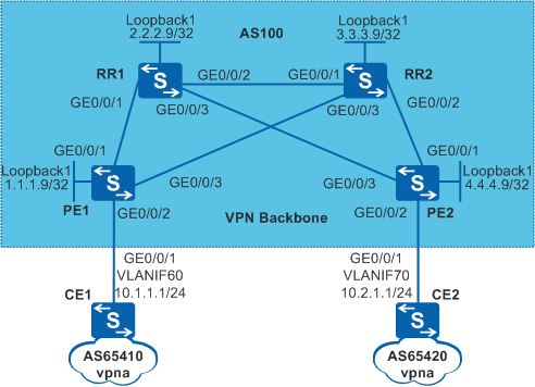
When deploying a VPN, you can configure double route reflectors (RRs) on the VPN. To achieve this, you need to select two RRs from the Ps in the same AS on the backbone network and ensure that the two RRs back up each other and reflect routes of the public network and VPNv4.
As shown in Figure 1, PE1, PE2, RR1, and RR2 are located in AS 100 on the backbone network. CE1 and CE2 belong to vpna. Select RR1 and RR2 as the RRs of the VPN.

In this scenario, to avoid loops, ensure that all connected interfaces have STP disabled and connected interfaces are removed from VLAN 1. If STP is enabled and VLANIF interfaces of switches are used to construct a Layer 3 ring network, an interface on the network will be blocked. As a result, Layer 3 services on the network cannot run normally.
Switch |
Interface |
VLANIF Interface |
IP Address |
|---|---|---|---|
PE1 |
GE0/0/1 |
VLANIF10 |
100.1.2.1/24 |
PE1 |
GE0/0/2 |
VLANIF60 |
10.1.1.2/24 |
PE1 |
GE0/0/3 |
VLANIF40 |
100.1.3.1/24 |
PE2 |
GE0/0/1 |
VLANIF30 |
100.3.4.2/24 |
PE2 |
GE0/0/2 |
VLANIF70 |
10.2.1.2/24 |
PE2 |
GE0/0/3 |
VLANIF50 |
100.2.4.2/24 |
RR1 |
GE0/0/1 |
VLANIF10 |
100.1.2.2/24 |
RR1 |
GE0/0/2 |
VLANIF20 |
100.2.3.1/24 |
RR1 |
GE0/0/3 |
VLANIF50 |
100.2.4.1/24 |
RR2 |
GE0/0/1 |
VLANIF20 |
100.2.3.2/24 |
RR2 |
GE0/0/2 |
VLANIF30 |
100.3.4.1/24 |
RR2 |
GE0/0/3 |
VLANIF40 |
100.1.3.2/24 |
Configuration Roadmap
The configuration roadmap is as follows:
- Configure an IGP protocol on the MPLS backbone network for IP connectivity.
- Configure basic MPLS capabilities and MPLS LDP on the backbone network to establish MPLS LSPs.
- Configure VPN instances on PE1 and PE2 and bind the interfaces connected to the CEs to the VPN instances. Configure the same VPN target for the VPN instances to enable users in the same VPN to communicate with each other.
- Establish EBGP peer relationships between PEs and CEs and import VPN routes into BGP.
- Establish MP-IBGP peer relationships between PEs and RRs. No MP-IBGP peer relationship is required between the PEs.
- Configure the same reflector cluster ID for RR1 and RR2 so that they back up each other.
- Configure RR1 and RR2 to accept all VPNv4 routes without filtering the routes based on VPN targets, because RR1 and RR2 must save all VPNv4 routes and advertise them to PEs.
On a VPN with double RRs, ensure that each RR has at least two paths to a PE and the paths do not share the same network segment or node. If there is only one path between the RRs and PEs or if the paths share the same network segment or node, double RRs cannot improve network reliability.
Procedure
- Configure VLANs on interfaces and assign IP addresses to
the VLANIF interfaces and loopback interfaces according to Figure 1.
# Configure PE1. The configuration on PE2, RRs, CE1, and CE2 is similar to the configuration on PE1 and is not mentioned here.
<HUAWEI> system-view
[HUAWEI] sysname PE1
[PE1] interface loopback 1
[PE1-LoopBack1] ip address 1.1.1.9 32
[PE1-LoopBack1] quit
[PE1] vlan batch 10 40 60
[PE1] interface gigabitethernet 0/0/1
[PE1-GigabitEthernet0/0/1] port link-type trunk
[PE1-GigabitEthernet0/0/1] port trunk allow-pass vlan 10
[PE1-GigabitEthernet0/0/1] quit
[PE1] interface gigabitethernet 0/0/2
[PE1-GigabitEthernet0/0/2] port link-type trunk
[PE1-GigabitEthernet0/0/2] port trunk allow-pass vlan 60
[PE1-GigabitEthernet0/0/2] quit
[PE1] interface gigabitethernet 0/0/3
[PE1-GigabitEthernet0/0/3] port link-type trunk
[PE1-GigabitEthernet0/0/3] port trunk allow-pass vlan 40
[PE1-GigabitEthernet0/0/3] quit
[PE1] interface vlanif 10
[PE1-Vlanif10] ip address 100.1.2.1 24
[PE1-Vlanif10] quit
[PE1] interface vlanif 40
[PE1-Vlanif40] ip address 100.1.3.1 24
[PE1-Vlanif40] quit
- Configure an IGP protocol on the MPLS backbone network
for IP connectivity.
# Configure PE1. The configuration on PE2 and RRs is similar to the configuration on PE1 and is not mentioned here.
[PE1] ospf
[PE1-ospf-1] area 0
[PE1-ospf-1-area-0.0.0.0] network 1.1.1.9 0.0.0.0
[PE1-ospf-1-area-0.0.0.0] network 100.1.2.0 0.0.0.255
[PE1-ospf-1-area-0.0.0.0] network 100.1.3.0 0.0.0.255
[PE1-ospf-1-area-0.0.0.0] quit
[PE1-ospf-1] quit
The IP addresses of loopback interfaces that are used as LSR IDs need to be advertised.
After the configuration is complete, the devices on the backbone network can obtain the loopback interface addresses from each other.
The information displayed on PE1 is used as an example.
[PE1] display ip routing-table Route Flags: R - relay, D - download to fib, T - to vpn-instance ------------------------------------------------------------------------------ Routing Tables: Public Destinations : 13 Routes : 15 Destination/Mask Proto Pre Cost Flags NextHop Interface 1.1.1.9/32 Direct 0 0 D 127.0.0.1 LoopBack1 2.2.2.9/32 OSPF 10 1 D 100.1.2.2 Vlanif10 3.3.3.9/32 OSPF 10 1 D 100.1.3.2 Vlanif40 4.4.4.9/32 OSPF 10 2 D 100.1.2.2 Vlanif10 OSPF 10 2 D 100.1.3.2 Vlanif40 100.1.2.0/24 Direct 0 0 D 100.1.2.1 Vlanif10 100.1.2.1/32 Direct 0 0 D 127.0.0.1 Vlanif10 100.1.3.0/24 Direct 0 0 D 100.1.3.1 Vlanif40 100.1.3.1/32 Direct 0 0 D 127.0.0.1 Vlanif40 100.2.3.0/24 OSPF 10 2 D 100.1.3.2 Vlanif40 OSPF 10 2 D 100.1.2.2 Vlanif10 100.2.4.0/24 OSPF 10 2 D 100.1.2.2 Vlanif10 100.3.4.0/24 OSPF 10 2 D 100.1.3.2 Vlanif40 127.0.0.0/8 Direct 0 0 D 127.0.0.1 InLoopBack0 127.0.0.1/32 Direct 0 0 D 127.0.0.1 InLoopBack0 - Configure basic MPLS capabilities and MPLS LDP on the MPLS
backbone network to establish LDP LSPs.
# Configure PE1. The configuration on PE2 and RRs is similar to the configuration on PE1 and is not mentioned here.
[PE1] mpls lsr-id 1.1.1.9
[PE1] mpls
[PE1-mpls] quit
[PE1] mpls ldp
[PE1-mpls-ldp] quit
[PE1] interface vlanif 10
[PE1-Vlanif10] mpls
[PE1-Vlanif10] mpls ldp
[PE1-Vlanif10] quit
[PE1] interface vlanif 40
[PE1-Vlanif40] mpls
[PE1-Vlanif40] mpls ldp
[PE1-Vlanif40] quit
After the configuration is complete, run the display mpls ldp session command on the PEs and RRs. The Status field in the command output displays as Operational.
PE1 and RR1 are used as an example.
[PE1] display mpls ldp session

 LDP Session(s) in Public Network
 Codes: LAM(Label Advertisement Mode), SsnAge Unit(DDDD:HH:MM)
 A '*' before a session means the session is being deleted.
------------------------------------------------------------------------------
 PeerID             Status      LAM  SsnRole  SsnAge      KASent/Rcv
------------------------------------------------------------------------------
 2.2.2.9:0          Operational DU   Passive  0000:00:01  8/8
 3.3.3.9:0          Operational DU   Passive  0000:00:00  4/4
------------------------------------------------------------------------------
 TOTAL: 2 session(s) Found.
[RR1] display mpls ldp session

 LDP Session(s) in Public Network
 Codes: LAM(Label Advertisement Mode), SsnAge Unit(DDDD:HH:MM)
 A '*' before a session means the session is being deleted.
------------------------------------------------------------------------------
 PeerID             Status      LAM  SsnRole  SsnAge      KASent/Rcv
------------------------------------------------------------------------------
 1.1.1.9:0          Operational DU   Active   000:00:02   11/11
 3.3.3.9:0          Operational DU   Passive  000:00:01   8/8
 4.4.4.9:0          Operational DU   Passive  000:00:00   4/4
------------------------------------------------------------------------------
 TOTAL: 3 session(s) Found.
- Configure VPN instances on the PEs.
# Configure PE1. The configuration on PE2 is similar to the configuration on PE1 and is not mentioned here.
[PE1] ip vpn-instance vpna
[PE1-vpn-instance-vpna] ipv4-family
[PE1-vpn-instance-vpna-af-ipv4] route-distinguisher 100:1
[PE1-vpn-instance-vpna-af-ipv4] vpn-target 1:1 both
[PE1-vpn-instance-vpna-af-ipv4] quit
[PE1-vpn-instance-vpna] quit
[PE1] interface vlanif 60
[PE1-Vlanif60] ip binding vpn-instance vpna
[PE1-Vlanif60] ip address 10.1.1.2 24
[PE1-Vlanif60] quit
- Establish EBGP peer relationships between PEs and CEs and
import VPN routes into BGP.
# Configure CE1. The configuration on CE2 is similar to the configuration on CE1 and is not mentioned here.
[CE1] bgp 65410
[CE1-bgp] peer 10.1.1.2 as-number 100
[CE1-bgp] quit
# Configure PE1. The configuration on PE2 is similar to the configuration on PE1 and is not mentioned here.
[PE1] bgp 100
[PE1-bgp] ipv4-family vpn-instance vpna
[PE1-bgp-vpna] peer 10.1.1.1 as-number 65410
[PE1-bgp-vpna] import-route direct
[PE1-bgp-vpna] quit
[PE1-bgp] quit
- Establish MP-IBGP peer relationships between PEs and RRs.
# Configure PE1. The configuration on PE2 is similar to the configuration on PE1 and is not mentioned here.
[PE1] bgp 100
[PE1-bgp] peer 2.2.2.9 as-number 100
[PE1-bgp] peer 2.2.2.9 connect-interface loopback 1
[PE1-bgp] peer 3.3.3.9 as-number 100
[PE1-bgp] peer 3.3.3.9 connect-interface loopback 1
[PE1-bgp] ipv4-family vpnv4
[PE1-bgp-af-vpnv4] peer 2.2.2.9 enable
[PE1-bgp-af-vpnv4] peer 3.3.3.9 enable
[PE1-bgp-af-vpnv4] quit
[PE1-bgp] quit
# Configure RR1.
[RR1] bgp 100
[RR1-bgp] group rr1 internal
[RR1-bgp] peer rr1 connect-interface loopback 1
[RR1-bgp] peer 1.1.1.9 group rr1
[RR1-bgp] peer 3.3.3.9 group rr1
[RR1-bgp] peer 4.4.4.9 group rr1
[RR1-bgp] ipv4-family vpnv4
[RR1-bgp-af-vpnv4] peer rr1 enable
[RR1-bgp-af-vpnv4] peer 1.1.1.9 group rr1
[RR1-bgp-af-vpnv4] peer 3.3.3.9 group rr1
[RR1-bgp-af-vpnv4] peer 4.4.4.9 group rr1
[RR1-bgp-af-vpnv4] quit
[RR1-bgp] quit
# Configure RR2.
[RR2] bgp 100
[RR2-bgp] group rr2 internal
[RR2-bgp] peer rr2 connect-interface loopback 1
[RR2-bgp] peer 1.1.1.9 group rr2
[RR2-bgp] peer 2.2.2.9 group rr2
[RR2-bgp] peer 4.4.4.9 group rr2
[RR2-bgp] ipv4-family vpnv4
[RR2-bgp-af-vpnv4] peer rr2 enable
[RR2-bgp-af-vpnv4] peer 1.1.1.9 group rr2
[RR2-bgp-af-vpnv4] peer 2.2.2.9 group rr2
[RR2-bgp-af-vpnv4] peer 4.4.4.9 group rr2
[RR2-bgp-af-vpnv4] quit
[RR2-bgp] quit
After the configuration is complete, run the display bgp vpnv4 all peer command on the PEs. The command output shows that the PEs have established IBGP peer relationships with RRs, and the peer relationships are in Established state. The PEs also establish EBGP peer relationships with CEs.
The information displayed on PE1 is used as an example.
[PE1] display bgp vpnv4 all peer BGP local router ID : 1.1.1.9 Local AS number : 100 Total number of peers : 3 Peers in established state : 3 Peer V AS MsgRcvd MsgSent OutQ Up/Down State PrefRcv 2.2.2.9 4 100 2 4 0 00:00:31 Established 0 3.3.3.9 4 100 3 5 0 00:01:23 Established 0 Peer of IPv4-family for vpn instance : VPN-Instance vpna, Router ID 1.1.1.9: 10.1.1.1 4 65410 79 82 0 01:13:29 Established 0 - Configure route reflection on RR1 and RR2.
# Configure RR1.
[RR1] bgp 100
[RR1-bgp] ipv4-family vpnv4
[RR1-bgp-af-vpnv4] reflector cluster-id 100
[RR1-bgp-af-vpnv4] peer rr1 reflect-client
[RR1-bgp-af-vpnv4] undo policy vpn-target
[RR1-bgp-af-vpnv4] quit
[RR1-bgp] quit
# Configure RR2.
[RR2] bgp 100
[RR2-bgp] ipv4-family vpnv4
[RR2-bgp-af-vpnv4] reflector cluster-id 100
[RR2-bgp-af-vpnv4] peer rr2 reflect-client
[RR2-bgp-af-vpnv4] undo policy vpn-target
[RR2-bgp-af-vpnv4] quit
[RR2-bgp] quit
- Verify the configurations.
Check the VPN routing table on a PE. The routing table contains a route to the remote CE.
The information displayed on PE1 is used as an example.
[PE1] display ip routing-table vpn-instance vpna
Route Flags: R - relay, D - download to fib, T - to vpn-instance
------------------------------------------------------------------------------
Routing Tables: vpna
         Destinations : 3        Routes : 3

  Destination/Mask  Proto  Pre  Cost         Flags  NextHop         Interface

       10.1.1.0/24  Direct 0    0                D  10.1.1.2        Vlanif60
       10.1.1.2/32  Direct 0    0                D  127.0.0.1       Vlanif60
       10.2.1.0/24  IBGP   255  0               RD  4.4.4.9         Vlanif10
If CE1 and CE2 can ping each other, the route reflection function has been configured successfully.
Run the shutdown command on VLANIF40 of PE1 and VLANIF50 of PE2 to simulate a link failure. CE1 and CE2 can still ping each other, indicating that the RRs are successfully configured.
Configuration Files
PE1 configuration file
#
sysname PE1
#
vlan batch 10 40 60
#
ip vpn-instance vpna
 ipv4-family
  route-distinguisher 100:1
  vpn-target 1:1 export-extcommunity
  vpn-target 1:1 import-extcommunity
#
mpls lsr-id 1.1.1.9
mpls
#
mpls ldp
#
interface Vlanif10
 ip address 100.1.2.1 255.255.255.0
 mpls
 mpls ldp
#
interface Vlanif40
 ip address 100.1.3.1 255.255.255.0
 mpls
 mpls ldp
#
interface Vlanif60
 ip binding vpn-instance vpna
 ip address 10.1.1.2 255.255.255.0
#
interface GigabitEthernet0/0/1
 port link-type trunk
 port trunk allow-pass vlan 10
#
interface GigabitEthernet0/0/2
 port link-type trunk
 port trunk allow-pass vlan 60
#
interface GigabitEthernet0/0/3
 port link-type trunk
 port trunk allow-pass vlan 40
#
interface LoopBack1
 ip address 1.1.1.9 255.255.255.255
#
bgp 100
 peer 2.2.2.9 as-number 100
 peer 2.2.2.9 connect-interface LoopBack1
 peer 3.3.3.9 as-number 100
 peer 3.3.3.9 connect-interface LoopBack1
 #
 ipv4-family unicast
  undo synchronization
  peer 2.2.2.9 enable
  peer 3.3.3.9 enable
 #
 ipv4-family vpnv4
  policy vpn-target
  peer 2.2.2.9 enable
  peer 3.3.3.9 enable
 #
 ipv4-family vpn-instance vpna
  import-route direct
  peer 10.1.1.1 as-number 65410
#
ospf 1
 area 0.0.0.0
  network 1.1.1.9 0.0.0.0
  network 100.1.2.0 0.0.0.255
  network 100.1.3.0 0.0.0.255
#
return
RR1 configuration file
#
sysname RR1
#
vlan batch 10 20 50
#
mpls lsr-id 2.2.2.9
mpls
#
mpls ldp
#
interface Vlanif10
 ip address 100.1.2.2 255.255.255.0
 mpls
 mpls ldp
#
interface Vlanif20
 ip address 100.2.3.1 255.255.255.0
 mpls
 mpls ldp
#
interface Vlanif50
 ip address 100.2.4.1 255.255.255.0
 mpls
 mpls ldp
#
interface GigabitEthernet0/0/1
 port link-type trunk
 port trunk allow-pass vlan 10
#
interface GigabitEthernet0/0/2
 port link-type trunk
 port trunk allow-pass vlan 20
#
interface GigabitEthernet0/0/3
 port link-type trunk
 port trunk allow-pass vlan 50
#
interface LoopBack1
 ip address 2.2.2.9 255.255.255.255
#
bgp 100
 group rr1 internal
 peer rr1 connect-interface LoopBack1
 peer 1.1.1.9 as-number 100
 peer 1.1.1.9 group rr1
 peer 3.3.3.9 as-number 100
 peer 3.3.3.9 group rr1
 peer 4.4.4.9 as-number 100
 peer 4.4.4.9 group rr1
 #
 ipv4-family unicast
  undo synchronization
  peer rr1 enable
  peer 1.1.1.9 enable
  peer 1.1.1.9 group rr1
  peer 3.3.3.9 enable
  peer 3.3.3.9 group rr1
  peer 4.4.4.9 enable
  peer 4.4.4.9 group rr1
 #
 ipv4-family vpnv4
  reflector cluster-id 100
  undo policy vpn-target
  peer rr1 enable
  peer rr1 reflect-client
  peer 1.1.1.9 enable
  peer 1.1.1.9 group rr1
  peer 3.3.3.9 enable
  peer 3.3.3.9 group rr1
  peer 4.4.4.9 enable
  peer 4.4.4.9 group rr1
#
ospf 1
 area 0.0.0.0
  network 2.2.2.9 0.0.0.0
  network 100.1.2.0 0.0.0.255
  network 100.2.3.0 0.0.0.255
  network 100.2.4.0 0.0.0.255
#
return
RR2 configuration file
#
sysname RR2
#
vlan batch 20 30 40
#
mpls lsr-id 3.3.3.9
mpls
#
mpls ldp
#
interface Vlanif20
 ip address 100.2.3.2 255.255.255.0
 mpls
 mpls ldp
#
interface Vlanif30
 ip address 100.3.4.1 255.255.255.0
 mpls
 mpls ldp
#
interface Vlanif40
 ip address 100.1.3.2 255.255.255.0
 mpls
 mpls ldp
#
interface GigabitEthernet0/0/1
 port link-type trunk
 port trunk allow-pass vlan 20
#
interface GigabitEthernet0/0/2
 port link-type trunk
 port trunk allow-pass vlan 30
#
interface GigabitEthernet0/0/3
 port link-type trunk
 port trunk allow-pass vlan 40
#
interface LoopBack1
 ip address 3.3.3.9 255.255.255.255
#
bgp 100
 group rr2 internal
 peer rr2 connect-interface LoopBack1
 peer 1.1.1.9 as-number 100
 peer 1.1.1.9 group rr2
 peer 2.2.2.9 as-number 100
 peer 2.2.2.9 group rr2
 peer 4.4.4.9 as-number 100
 peer 4.4.4.9 group rr2
 #
 ipv4-family unicast
  undo synchronization
  peer rr2 enable
  peer 1.1.1.9 enable
  peer 1.1.1.9 group rr2
  peer 2.2.2.9 enable
  peer 2.2.2.9 group rr2
  peer 4.4.4.9 enable
  peer 4.4.4.9 group rr2
 #
 ipv4-family vpnv4
  reflector cluster-id 100
  undo policy vpn-target
  peer rr2 enable
  peer rr2 reflect-client
  peer 1.1.1.9 enable
  peer 1.1.1.9 group rr2
  peer 2.2.2.9 enable
  peer 2.2.2.9 group rr2
  peer 4.4.4.9 enable
  peer 4.4.4.9 group rr2
#
ospf 1
 area 0.0.0.0
  network 3.3.3.9 0.0.0.0
  network 100.1.3.0 0.0.0.255
  network 100.2.3.0 0.0.0.255
  network 100.3.4.0 0.0.0.255
#
return
PE2 configuration file
#
sysname PE2
#
vlan batch 30 50 70
#
ip vpn-instance vpna
 ipv4-family
  route-distinguisher 100:1
  vpn-target 1:1 export-extcommunity
  vpn-target 1:1 import-extcommunity
#
mpls lsr-id 4.4.4.9
mpls
#
mpls ldp
#
interface Vlanif30
 ip address 100.3.4.2 255.255.255.0
 mpls
 mpls ldp
#
interface Vlanif50
 ip address 100.2.4.2 255.255.255.0
 mpls
 mpls ldp
#
interface Vlanif70
 ip binding vpn-instance vpna
 ip address 10.2.1.2 255.255.255.0
#
interface GigabitEthernet0/0/1
 port link-type trunk
 port trunk allow-pass vlan 30
#
interface GigabitEthernet0/0/2
 port link-type trunk
 port trunk allow-pass vlan 70
#
interface GigabitEthernet0/0/3
 port link-type trunk
 port trunk allow-pass vlan 50
#
interface LoopBack1
 ip address 4.4.4.9 255.255.255.255
#
bgp 100
 peer 2.2.2.9 as-number 100
 peer 2.2.2.9 connect-interface LoopBack1
 peer 3.3.3.9 as-number 100
 peer 3.3.3.9 connect-interface LoopBack1
 #
 ipv4-family unicast
  undo synchronization
  peer 2.2.2.9 enable
  peer 3.3.3.9 enable
 #
 ipv4-family vpnv4
  policy vpn-target
  peer 2.2.2.9 enable
  peer 3.3.3.9 enable
 #
 ipv4-family vpn-instance vpna
  import-route direct
  peer 10.2.1.1 as-number 65420
#
ospf 1
 area 0.0.0.0
  network 4.4.4.9 0.0.0.0
  network 100.2.4.0 0.0.0.255
  network 100.3.4.0 0.0.0.255
#
return
CE1 configuration file
#
sysname CE1
#
vlan batch 60
#
interface Vlanif60
 ip address 10.1.1.1 255.255.255.0
#

interface GigabitEthernet0/0/1
 port link-type trunk
 port trunk allow-pass vlan 60
#
bgp 65410
 peer 10.1.1.2 as-number 100
 #
 ipv4-family unicast
  undo synchronization
  peer 10.1.1.2 enable
#
return
CE2 configuration file
#
sysname CE2
#
vlan batch 70
#
interface Vlanif70
 ip address 10.2.1.1 255.255.255.0
#
interface GigabitEthernet0/0/1
 port link-type trunk
 port trunk allow-pass vlan 70
#
bgp 65420
 peer 10.2.1.2 as-number 100
 #
 ipv4-family unicast
  undo synchronization
  peer 10.2.1.2 enable
#
return