Example for Configuring CE Dual-Homing
Networking Requirements
It is a trend to transmit all telecommunication services on an IP network. Key services such as 3G/NGN, IPTV streaming media, and VPN services require very high reliability on networks. In addition to improving the reliability of the network devices, you can improve the link reliability by configuring fast route convergence, fault detection, fast reroute, and route backup.
On the access layer, the CE dual-homing networking is a common method to improve the network reliability. A dual-homed CE connects to two PEs that belong to the same VPN. In this networking, the CE connects to the backbone network through two links. The two links work in load balancing mode or active/standby mode.
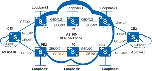
As shown in Figure 1, CE1 is located in site1 of vpn1, and CE2 is located in site2 of vpn1. CE1 connects to PE1 and PE2, and CE2 connects to PE3 and PE4.
If the data traffic volume from CE1 to CE2 is large but traffic volume from CE2 to CE1 is small, the data traffic from CE1 to CE2 can be transmitted in load balancing mode. The data traffic from CE2 to CE1 is transmitted through PE4, and PE3 only works as a backup.

In this scenario, to avoid loops, ensure that all connected interfaces have STP disabled and connected interfaces are removed from VLAN 1. If STP is enabled and VLANIF interfaces of switches are used to construct a Layer 3 ring network, an interface on the network will be blocked. As a result, Layer 3 services on the network cannot run normally.
Switch |
Interface |
VLANIF Interface |
IP Address |
|---|---|---|---|
PE1 |
Loopback1 |
- |
1.1.1.1/32 |
PE1 |
GE0/0/1 |
VLANIF101 |
2001::2/64 |
PE1 |
GE0/0/2 |
VLANIF10 |
100.1.1.1/30 |
PE2 |
Loopback1 |
- |
2.2.2.2/32 |
PE2 |
GE0/0/1 |
VLANIF102 |
2002::2/64 |
PE2 |
GE0/0/2 |
VLANIF20 |
100.2.1.1/30 |
P1 |
Loopback1 |
- |
5.5.5.5/32 |
P1 |
GE0/0/1 |
VLANIF10 |
100.1.1.2/30 |
P1 |
GE0/0/2 |
VLANIF30 |
100.3.1.1/30 |
P2 |
Loopback1 |
- |
6.6.6.6/32 |
P2 |
GE0/0/1 |
VLANIF20 |
100.2.1.2/30 |
P2 |
GE0/0/2 |
VLANIF40 |
100.4.1.1/30 |
PE3 |
Loopback1 |
- |
3.3.3.3/32 |
PE3 |
GE0/0/1 |
VLANIF30 |
100.3.1.2/30 |
PE3 |
GE0/0/2 |
VLANIF103 |
2003::2/64 |
PE4 |
Loopback1 |
- |
4.4.4.4/32 |
PE4 |
GE0/0/1 |
VLANIF40 |
100.4.1.2/30 |
PE4 |
GE0/0/2 |
VLANIF104 |
2004::2/64 |
CE1 |
GE0/0/1 |
VLANIF101 |
2001::1/64 |
CE1 |
GE0/0/2 |
VLANIF102 |
2002::1/64 |
CE1 |
GE0/0/3 |
VLANIF1001 |
2005::1/64 |
CE2 |
GE0/0/1 |
VLANIF103 |
2003::1/64 |
CE2 |
GE0/0/2 |
VLANIF104 |
2004::1/64 |
CE2 |
GE0/0/3 |
VLANIF1002 |
2006::1/64 |
Configuration Roadmap
The configuration roadmap is as follows:
Configure basic BGP/MPLS IPv6 VPNs.
In the BGP view of CE1, configure load balancing for traffic sent to CE2.
Increase the MED value of the BGP-VPN route on PE3 to ensure that the next hop of the route selected by CE2 to the customer network connected to CE1 is PE4.
Procedure
- Create VLANs, configure the allowed VLANs on interfaces,
and assign IP addresses to the VLANIF interfaces and loopback interfaces
according to Figure 1.
# Configure PE1.
<HUAWEI> system-view
[HUAWEI] sysname PE1
[PE1] ipv6
[PE1] interface loopback 1
[PE1-LoopBack1] ip address 1.1.1.1 32
[PE1-LoopBack1] quit
[PE1] vlan batch 10 101
[PE1] interface gigabitethernet 0/0/1
[PE1-GigabitEthernet0/0/1] port link-type trunk
[PE1-GigabitEthernet0/0/1] port trunk allow-pass vlan 101
[PE1-GigabitEthernet0/0/1] quit
[PE1] interface gigabitethernet 0/0/2
[PE1-GigabitEthernet0/0/2] port link-type trunk
[PE1-GigabitEthernet0/0/2] port trunk allow-pass vlan 10
[PE1-GigabitEthernet0/0/2] quit
[PE1] interface vlanif 10
[PE1-Vlanif10] ip address 100.1.1.1 30
[PE1-Vlanif10] quit
The configuration on P1, P2, PE2, PE3, PE4, CE1, and CE2 is similar to the configuration on PE1 and is not mentioned here.
- Configure an IGP on the MPLS backbone network so that PEs
and Ps can communicate with each other.
IS-IS and PE1 are used as examples.
# Configure PE1.
[PE1] isis 1
[PE1-isis-1] network-entity 10.0000.0000.0001.00
[PE1-isis-1] quit
[PE1] interface loopback 1
[PE1-LoopBack1] isis enable 1
[PE1-LoopBack1] quit
[PE1] interface vlanif 10
[PE1-Vlanif10] isis enable 1
[PE1-Vlanif10] quit
The configuration on PE2, PE3, PE4, P1, and P2 is similar to the configuration on PE1 and is not mentioned here.
After the configuration is complete, run the display ip routing-table command. The command output shows that PE1 and PE3 can learn the routes of Loopback1 interface of each other; PE2 and PE4 can learn routes of Loopback1 interface of each other.
- Configure basic MPLS capabilities and MPLS LDP on the MPLS
backbone network to establish LDP LSPs.
# Configure PE1.
# Enable MPLS and LDP in the system view, set the LSR ID to the IP address of the loopback interface, and trigger the LSP.
[PE1] mpls lsr-id 1.1.1.1
[PE1] mpls
[PE1-mpls] quit
[PE1] mpls ldp
[PE1-mpls-ldp] quit
# Enable MPLS and LDP on the interface connected to the backbone network.
[PE1] interface vlanif 10
[PE1-Vlanif10] mpls
[PE1-Vlanif10] mpls ldp
[PE1-Vlanif10] quit
# The configuration on PE2, PE3, PE4, P1, and P2 is similar to the configuration on PE1 and is not mentioned here.
After the configuration is complete, LDP sessions can be established between PE1 and the P, and between the P and PE2. Run the display mpls ldp session command. The command output shows that the Status field is Operational. Run the display mpls ldp lsp command. Information about the established LDP LSP is displayed.
The information displayed on PE1 is used as an example.
[PE1] display mpls ldp session LDP Session(s) in Public Network Codes: LAM(Label Advertisement Mode), SsnAge Unit(DDDD:HH:MM) A '*' before a session means the session is being deleted. ------------------------------------------------------------------------------ PeerID Status LAM SsnRole SsnAge KASent/Rcv ------------------------------------------------------------------------------ 5.5.5.5:0 Operational DU Active 0000:09:10 2201/2185 ------------------------------------------------------------------------------ TOTAL: 1 session(s) Found. [PE1] display mpls ldp lsp LDP LSP Information ------------------------------------------------------------------------------- Flag after Out IF: (I) - LSP Is Only Iterated by RLFA ------------------------------------------------------------------------------- DestAddress/Mask In/OutLabel UpstreamPeer NextHop OutInterface ------------------------------------------------------------------------------- 1.1.1.1/32 3/NULL 5.5.5.5 127.0.0.1 InLoop0 *1.1.1.1/32 Liberal/1024 DS/5.5.5.5 3.3.3.3/32 NULL/1025 - 10.1.1.2 Vlanif10 3.3.3.3/32 1025/1025 5.5.5.5 10.1.1.2 Vlanif10 5.5.5.5/32 NULL/3 - 10.1.1.2 Vlanif10 5.5.5.5/32 1024/3 5.5.5.5 10.1.1.2 Vlanif10 ----------------------------------------------------------------------------- TOTAL: 5 Normal LSP(s) Found. TOTAL: 1 Liberal LSP(s) Found. TOTAL: 0 Frr LSP(s) Found. A '*' before an LSP means the LSP is not established A '*' before a Label means the USCB or DSCB is stale A '*' before a UpstreamPeer means the session is stale A '*' before a DS means the session is stale A '*' before a NextHop means the LSP is FRR LSP - Configure IPv6 VPN instances on PEs and bind the interfaces
connected to CEs to the VPN instances.
# Configure PE1.
# Create a VPN instance, and set the RD and VPN target of the VPN instance. The VPN target set on the local PE must match the VPN target of the MP-BGP peer PE so that the sites of the same VPN can communicate with each other.
[PE1] ipv6
[PE1] ip vpn-instance vpn1
[PE1-vpn-instance-vpn1] ipv6-family
[PE1-vpn-instance-vpn1-af-ipv6] route-distinguisher 100:1
[PE1-vpn-instance-vpn1-af-ipv6] vpn-target 1:1 both
[PE1-vpn-instance-vpn1-af-ipv6] quit
[PE1-vpn-instance-vpn1] quit
# Bind the interface connected to CE1 to the corresponding VPN instance and set the IP address of the interface.
[PE1] interface vlanif 101
[PE1-Vlanif101] ipv6 enable
[PE1-Vlanif101] ip binding vpn-instance vpn1
[PE1-Vlanif101] ipv6 address 2001::2 64
[PE1-Vlanif101] quit
# Configure PE2.
# Enable IPv6, create a VPN instance, and set the RD and VPN target of the VPN instance. The VPN target set on the local PE must match the VPN target of the MP-BGP peer PE so that the sites of the same VPN can communicate with each other.
[PE2] ipv6
[PE2] ip vpn-instance vpn1
[PE2-vpn-instance-vpn1] ipv6-family
[PE2-vpn-instance-vpn1-af-ipv6] route-distinguisher 100:2
[PE2-vpn-instance-vpn1-af-ipv6] vpn-target 1:1 both
[PE2-vpn-instance-vpn1-af-ipv6] quit
[PE2-vpn-instance-vpn1] quit
# Bind the interface connected to CE1 to the corresponding VPN instance and set the IP address of the interface.
[PE2] interface vlanif 102
[PE2-Vlanif102] ipv6 enable
[PE2-Vlanif102] ip binding vpn-instance vpn1
[PE2-Vlanif102] ipv6 address 2002::2 64
[PE2-Vlanif102] quit
# Configure PE3.
# Enable IPv6, create a VPN instance, and set the RD and VPN target of the VPN instance. The VPN target set on the local PE must match the VPN target of the MP-BGP peer PE so that the sites of the same VPN can communicate with each other.
[PE3] ipv6
[PE3] ip vpn-instance vpn1
[PE3-vpn-instance-vpn1] ipv6-family
[PE3-vpn-instance-vpn1-af-ipv6] route-distinguisher 100:3
[PE3-vpn-instance-vpn1-af-ipv6] vpn-target 1:1 both
[PE3-vpn-instance-vpn1-af-ipv6] quit
[PE3-vpn-instance-vpn1] quit
# Bind the interface connected to CE2 to the corresponding VPN instance and set the IP address of the interface.
[PE3] interface vlanif 103
[PE3-Vlanif103] ipv6 enable
[PE3-Vlanif103] ip binding vpn-instance vpn1
[PE3-Vlanif103] ipv6 address 2003::2 64
[PE3-Vlanif103] quit
# Configure PE4.
# Enable IPv6, create a VPN instance, and set the RD and VPN target of the VPN instance. The VPN target set on the local PE must match the VPN target of the MP-BGP peer PE so that the sites of the same VPN can communicate with each other.
[PE4] ipv6
[PE4] ipv6 vpn-instance vpn1
[PE4-vpn-instance-vpn1] ipv6-family
[PE4-vpn-instance-vpn1-af-ipv6] route-distinguisher 100:4
[PE4-vpn-instance-vpn1-af-ipv6] vpn-target 1:1 both
[PE4-vpn-instance-vpn1-af-ipv6] quit
[PE4-vpn-instance-vpn1] quit
# Bind the interface connected to CE2 to the corresponding VPN instance and set the IP address of the interface.
[PE4] interface vlanif 104
[PE4-Vlanif104] ipv6 enable
[PE4-Vlanif104] ip binding vpn-instance vpn1
[PE4-Vlanif104] ipv6 address 2004::2 64
[PE4-Vlanif104] quit
# Assign IPv6 addresses to the interfaces on the CEs according to Figure 1. The configuration procedure is not mentioned here.
After the configuration is complete, run the display ip vpn-instance verbose command on the PEs to check the configuration of IPv6 VPN instances.
The information displayed on PE1 is used as an example.
[PE1] display ip vpn-instance verbose
 Total VPN-Instances configured      : 1
 Total IPv4 VPN-Instances configured : 0
 Total IPv6 VPN-Instances configured : 1

 VPN-Instance Name and ID : vpn1, 1
  Interfaces : Vlanif101
 Address family ipv6
  Create date : 2012-12-22 14:50:00+00:00
  Up time : 0 days, 03 hours, 12 minutes and 12 seconds
  Route Distinguisher : 100:1
  Export VPN Targets :  1:1
  Import VPN Targets :  1:1
  Label Policy : label per route
  Log Interval : 5
- Configure EBGP between the PEs and CEs to import the VPN
routes.
# Configure CE1.
# Enable BGP, specify PE1 and PE2 as EBGP peers, and import direct routes.
[CE1] bgp 65410
[CE1-bgp] router-id 10.10.10.10
[CE1-bgp] peer 2001::2 as-number 100
[CE1-bgp] peer 2002::2 as-number 100
[CE1-bgp] ipv6-family unicast
[CE1-bgp-af-ipv6] peer 2001::2 enable
[CE1-bgp-af-ipv6] peer 2002::2 enable
[CE1-bgp-af-ipv6] import-route direct
[CE1-bgp-af-ipv6] quit
[CE1-bgp] quit
# Configure PE1.
# Enable BGP, enter the BGP-VPN instance IPv6 address family view, specify CE1 as the EBGP peer, and import the direct route.
[PE1] bgp 100
[PE1-bgp] ipv6-family vpn-instance vpn1
[PE1-bgp6-vpn1] peer 2001::1 as-number 65410
[PE1-bgp6-vpn1] import-route direct
[PE1-bgp6-vpn1] quit
# Configure PE2.
# Enable BGP, enter the BGP-VPN instance IPv6 address family view, specify CE1 as the EBGP peer, and import the direct route.
[PE2] bgp 100
[PE2-bgp] ipv6-family vpn-instance vpn1
[PE2-bgp6-vpn1] peer 2002::1 as-number 65410
[PE2-bgp6-vpn1] import-route direct
[PE2-bgp6-vpn1] quit
# Configure CE2.
# Enable BGP, specify PE3 and PE4 as EBGP peers, and import direct routes.
[CE2] bgp 65420
[CE2-bgp] router-id 20.20.20.20
[CE2-bgp] peer 2003::2 as-number 100
[CE2-bgp] peer 2004::2 as-number 100
[CE2-bgp] ipv6-family unicast
[CE2-bgp-af-ipv6] peer 2003::2 enable
[CE2-bgp-af-ipv6] peer 2004::2 enable
[CE2-bgp-af-ipv6] import-route direct
[CE2-bgp-af-ipv6] quit
[CE2-bgp] quit
# Configure PE3.
# Enable BGP, enter the BGP-VPN instance IPv6 address family view, specify CE2 as the EBGP peer, and import the direct route.
[PE3] bgp 100
[PE3-bgp] ipv6-family vpn-instance vpn1
[PE3-bgp6-vpn1] peer 2003::1 as-number 65420
[PE3-bgp6-vpn1] import-route direct
[PE3-bgp6-vpn1] quit
# Configure PE4.
# Enable BGP, enter the BGP-VPN instance IPv6 address family view, specify CE2 as the EBGP peer, and import the direct route.
[PE4] bgp 100
[PE4-bgp] ipv6-family vpn-instance vpn1
[PE4-bgp6-vpn1] peer 2004::1 as-number 65420
[PE4-bgp6-vpn1] import-route direct
[PE4-bgp6-vpn1] quit
After the configuration is complete, run the display bgp vpnv6 vpn-instance vpn-instance-name peer command on the PEs, and you can see that BGP peer relationships have been established between the PEs and CEs and are in Established state. Each PE can ping its connected CE.
The information displayed on PE1 is used as an example.
[PE1] display bgp vpnv6 vpn-instance vpn1 peer BGP local router ID : 1.1.1.1 Local AS number : 100 Total number of peers : 1 Peers in established state : 1 Peer V AS MsgRcvd MsgSent OutQ Up/Down State PrefRcv 2001::1 4 65410 408 435 0 06:16:09 Established 5 [PE1] ping ipv6 vpn-instance vpn1 2001::1 PING 2001::1 : 56 data bytes, press CTRL_C to break Reply from 2001::1 bytes=56 Sequence=1 hop limit=64 time = 15 ms Reply from 2001::1 bytes=56 Sequence=2 hop limit=64 time = 16 ms Reply from 2001::1 bytes=56 Sequence=3 hop limit=64 time = 15 ms Reply from 2001::1 bytes=56 Sequence=4 hop limit=64 time = 32 ms Reply from 2001::1 bytes=56 Sequence=5 hop limit=64 time = 16 ms --- 2001::1 ping statistics --- 5 packet(s) transmitted 5 packet(s) received 0.00% packet loss round-trip min/avg/max = 15/18/32 ms - Establish MP-IBGP peer relationships between PEs.
# Configure PE1.
# Specify PE3 as the IGBP peer and use the IP address of the loopback interface to establish an IBGP connection with the peer.
[PE1] bgp 100
[PE1-bgp] peer 3.3.3.3 as-number 100
[PE1-bgp] peer 3.3.3.3 connect-interface loopback 1
# Enter the VPNv6 address family view and enable the local PE to exchange IPv6 VPN routing information with the peer.
[PE1-bgp] ipv6-family vpnv6
[PE1-bgp-af-vpnv6] peer 3.3.3.3 enable
[PE1-bgp-af-vpnv6] quit
# Configure PE3.
# Specify PE1 as the IGBP peer and use the IP address of the loopback interface to establish an IBGP connection with the peer.
[PE3] bgp 100
[PE3-bgp] peer 1.1.1.1 as-number 100
[PE3-bgp] peer 1.1.1.1 connect-interface loopback 1
# Enter the VPNv6 address family view and enable the local PE to exchange IPv6 VPN routing information with the peer.
[PE3-bgp] ipv6-family vpnv6
[PE3-bgp-af-vpnv6] peer 1.1.1.1 enable
[PE3-bgp-af-vpnv6] quit
# Configure PE2.
# Specify PE4 as the IGBP peer and use the IP address of the loopback interface to establish an IBGP connection with the peer.
[PE2] bgp 100
[PE2-bgp] peer 4.4.4.4 as-number 100
[PE2-bgp] peer 4.4.4.4 connect-interface loopback 1
# Enter the VPNv6 address family view and enable the local PE to exchange IPv6 VPN routing information with the peer.
[PE2-bgp] ipv6-family vpnv6
[PE2-bgp-af-vpnv6] peer 4.4.4.4 enable
[PE2-bgp-af-vpnv6] quit
# Configure PE4.
# Specify PE2 as the IGBP peer and use the IP address of the loopback interface to establish an IBGP connection with the peer.
[PE4] bgp 100
[PE4-bgp] peer 2.2.2.2 as-number 100
[PE4-bgp] peer 2.2.2.2 connect-interface loopback 1
# Enter the VPNv6 address family view and enable the local PE to exchange IPv6 VPN routing information with the peer.
[PE4-bgp] ipv6-family vpnv6
[PE4-bgp-af-vpnv6] peer 2.2.2.2 enable
[PE4-bgp-af-vpnv6] quit
After the configuration is complete, run the display bgp vpnv6 all peer command on the PEs. The command output shows that BGP peer relationships have been between the PEs and CEs and are in Established state.
[PE1] display bgp vpnv6 all peer
BGP local router ID : 1.1.1.1
 Local AS number : 100
 Total number of peers : 2                 Peers in established state : 2

  Peer            V    AS  MsgRcvd  MsgSent  OutQ  Up/Down       State PrefRcv

  3.3.3.3         4   100       70       81     0 01:00:23 Established       3

  Peer of IPv6-family for vpn instance :

 VPN-Instance vpn1, Router ID 1.1.1.1:
  2001::1         4 65410       16       12     0 00:06:42 Established       3
- On CE1, configure load balancing for the traffic sent from
CE1 to CE2.
[CE1] bgp 65410
[CE1-bgp] ipv6-family unicast
[CE1-bgp-af-ipv6] maximum load-balancing 2
- Configure a routing policy on PE3 to increase the MED value
of the BGP routes advertised to CE2. Then the traffic sent from CE2
to CE1 is forwarded by PE4, and PE3 is a backup of PE4.
[PE3] route-policy policy1 permit node 10
[PE3-route-policy] apply cost 120
[PE3-route-policy] quit
[PE3] bgp 100
[PE3-bgp] ipv6-family vpn-instance vpn1
[PE3-bgp6-vpn1] peer 2003::1 route-policy policy1 export
- Verify the configuration.
Run the display ipv6 routing-table command on CE2, and you can see the routes to the customer network connected to the CE1. The next hop of the route is 2004::2, IPv6 address of the interface that connects PE4 to CE2.
If the configuration is successful:
Run the display ipv6 routing-table command on CE1, and you can see the routes to the customer network connected to the CE2. The routes work in load balancing mode.
[CE1] display ipv6 routing-table
Routing Table : Public
         Destinations : 11       Routes : 12

 Destination  : ::1                             PrefixLength : 128
 NextHop      : ::1                             Preference   : 0
 Cost         : 0                               Protocol     : Direct
 RelayNextHop : ::                              TunnelID     : 0x0
 Interface    : InLoopBack0                     Flags        : D

 Destination  : 2001::                          PrefixLength : 64
 NextHop      : 2001::1                         Preference   : 0
 Cost         : 0                               Protocol     : Direct
 RelayNextHop : ::                              TunnelID     : 0x0
 Interface    : Vlanif101                       Flags        : D

 Destination  : 2001::1                         PrefixLength : 128
 NextHop      : ::1                             Preference   : 0
 Cost         : 0                               Protocol     : Direct
 RelayNextHop : ::                              TunnelID     : 0x0
 Interface    : InLoopBack0                     Flags        : D
 Interface    : Vlanif101                       Flags        : D

 Destination  : 2002::                          PrefixLength : 64
 NextHop      : 2002::1                         Preference   : 0
 Cost         : 0                               Protocol     : Direct
 RelayNextHop : ::                              TunnelID     : 0x0
 Interface    : Vlanif102                       Flags        : D

 Destination  : 2002::1                         PrefixLength : 128
 NextHop      : ::1                             Preference   : 0
 Cost         : 0                               Protocol     : Direct
 RelayNextHop : ::                              TunnelID     : 0x0
 Interface    : Vlanif102                       Flags        : D

 Destination  : 2003::                          PrefixLength : 64
 NextHop      : 2001::2                         Preference   : 255
 Cost         : 0                               Protocol     : EBGP
 RelayNextHop : ::                              TunnelID     : 0x0
 Interface    : Vlanif101                       Flags        : D

 Destination  : 2004::                          PrefixLength : 64
 NextHop      : 2002::2                         Preference   : 255
 Cost         : 0                               Protocol     : EBGP
 RelayNextHop : ::                              TunnelID     : 0x0
 Interface    : Vlanif102                       Flags        : D

 Destination  : 2005::                          PrefixLength : 64
 NextHop      : 2005::1                         Preference   : 0
 Cost         : 0                               Protocol     : Direct
 RelayNextHop : ::                              TunnelID     : 0x0
 Interface    : Vlanif1001                      Flags        : D

 Destination  : 2005::1                         PrefixLength : 128
 NextHop      : ::1                             Preference   : 0
 Cost         : 0                               Protocol     : Direct
 RelayNextHop : ::                              TunnelID     : 0x0
 Interface    : InLoopBack0                     Flags        : D
 Interface    : Vlanif1001                      Flags        : D

 Destination  : 2006::                          PrefixLength : 64
 NextHop      : 2001::2                         Preference   : 255
 Cost         : 0                               Protocol     : EBGP
 RelayNextHop : ::                              TunnelID     : 0x0
 Interface    : Vlanif101                       Flags        : D

 Destination  : 2006::                          PrefixLength : 64
 NextHop      : 2002::2                         Preference   : 255
 Cost         : 0                               Protocol     : EBGP
 RelayNextHop : ::                              TunnelID     : 0x0
 Interface    : Vlanif102                       Flags        : D

 Destination  : FE80::                          PrefixLength : 10
 NextHop      : ::                              Preference   : 0
 Cost         : 0                               Protocol     : Direct
 RelayNextHop : ::                              TunnelID     : 0x0
 Interface    : NULL0                           Flags        : D
Configuration Files
CE1 configuration file
#
 sysname CE1
#
 ipv6
#
 vlan batch 101 102 1001
#
interface Vlanif101
 ipv6 enable
 ipv6 address 2001::1/64
#
interface Vlanif102
 ipv6 enable
 ipv6 address 2002::1/64
#
interface Vlanif1001
 ipv6 enable
 ipv6 address 2005::1/64
#
interface GigabitEthernet0/0/1
 port link-type trunk
 port trunk allow-pass vlan 101
#
interface GigabitEthernet0/0/2
 port link-type trunk
 port trunk allow-pass vlan 102
#
interface GigabitEthernet0/0/3
 port link-type trunk
 port trunk allow-pass vlan 1001
#
bgp 65410
 router-id 10.10.10.10
 peer 2001::2 as-number 100
 peer 2002::2 as-number 100
 #
 ipv6-family unicast
  undo synchronization
  import-route direct
  maximum load-balancing 2
  peer 2001::2 enable
  peer 2002::2 enable
#
return
PE1 configuration file
#
 sysname PE1
#
 ipv6
#
 vlan batch 10 101
#
ip vpn-instance vpn1
 ipv6-family
  route-distinguisher 100:1
  vpn-target 1:1 export-extcommunity
  vpn-target 1:1 import-extcommunity
#
mpls lsr-id 1.1.1.1
mpls
#
mpls ldp
#
isis 1
 network-entity 10.0000.0000.0001.00
#
interface Vlanif10
 ip address 100.1.1.1 255.255.255.252
 isis enable 1
 mpls
 mpls ldp
#
interface Vlanif101
 ipv6 enable
 ip binding vpn-instance vpn1
 ipv6 address 2001::2/64
#
interface GigabitEthernet0/0/1
 port link-type trunk
 port trunk allow-pass vlan 101
#
interface GigabitEthernet0/0/2
 port link-type trunk
 port trunk allow-pass vlan 10
#
interface LoopBack1
 ip address 1.1.1.1 255.255.255.255
 isis enable 1
#
bgp 100
 peer 3.3.3.3 as-number 100
 peer 3.3.3.3 connect-interface LoopBack1
 #
 ipv4-family unicast
  undo synchronization
  peer 3.3.3.3 enable
 #
 ipv6-family vpnv6
  policy vpn-target
  peer 3.3.3.3 enable
 #
 ipv6-family vpn-instance vpn1
  peer 2001::1 as-number 65410
  import-route direct
#
return
PE2 configuration file
#
 sysname PE2
#
 ipv6
#
 vlan batch 20 102
#
ip vpn-instance vpn1
 ipv6-family
  route-distinguisher 100:2
  vpn-target 1:1 export-extcommunity
  vpn-target 1:1 import-extcommunity
#
mpls lsr-id 2.2.2.2
mpls
#
mpls ldp
#
isis 1
 network-entity 10.0000.0000.0002.00
#
interface Vlanif20
 ip address 100.2.1.1 255.255.255.252
 isis enable 1
 mpls
 mpls ldp
#
interface Vlanif102
 ipv6 enable
 ip binding vpn-instance vpn1
 ipv6 address 2002::2/64
#
interface GigabitEthernet0/0/1
 port link-type trunk
 port trunk allow-pass vlan 102
#
interface GigabitEthernet0/0/2
 port link-type trunk
 port trunk allow-pass vlan 20
#
interface LoopBack1
 ip address 2.2.2.2 255.255.255.255
 isis enable 1
#
bgp 100
 peer 4.4.4.4 as-number 100
 peer 4.4.4.4 connect-interface LoopBack1
 #
 ipv4-family unicast
  undo synchronization
  peer 4.4.4.4 enable
 #
 ipv6-family vpnv6
  policy vpn-target
  peer 4.4.4.4 enable
 #
 ipv6-family vpn-instance vpn1
  peer 2002::1 as-number 65410
  import-route direct
#
return
P1 configuration file
#
 sysname P1
#
 vlan batch 10 30
#
mpls lsr-id 5.5.5.5
mpls
#
mpls ldp
#
isis 1
 network-entity 10.0000.0000.0005.00
#
interface Vlanif10
 ip address 100.1.1.2 255.255.255.252
 isis enable 1
 mpls
 mpls ldp
#
interface Vlanif30
 ip address 100.3.1.1 255.255.255.252
 isis enable 1
 mpls
 mpls ldp
#
interface GigabitEthernet0/0/1
 port link-type trunk
 port trunk allow-pass vlan 10
#
interface GigabitEthernet0/0/2
 port link-type trunk
 port trunk allow-pass vlan 30
#
interface LoopBack1
 ip address 5.5.5.5 255.255.255.255
 isis enable 1
#
return
P2 configuration file
#
 sysname P2
#
 vlan batch 20 40
#
mpls lsr-id 6.6.6.6
mpls
#
mpls ldp
#
isis 1
 network-entity 10.0000.0000.0006.00
#
interface Vlanif20
 ip address 100.2.1.2 255.255.255.252
 isis enable 1
 mpls
 mpls ldp
#
interface Vlanif40
 ip address 100.4.1.1 255.255.255.252
 isis enable 1
 mpls
 mpls ldp
#
interface GigabitEthernet0/0/1
 port link-type trunk
 port trunk allow-pass vlan 20
#
interface GigabitEthernet0/0/2
 port link-type trunk
 port trunk allow-pass vlan 40
#
interface LoopBack1
 ip address 6.6.6.6 255.255.255.255
 isis enable 1
#
return
PE3 configuration file
sysname PE3
#
 ipv6
#
 vlan batch 30 103
#
ip vpn-instance vpn1
 ipv6-family
  route-distinguisher 100:3
  vpn-target 1:1 export-extcommunity
  vpn-target 1:1 import-extcommunity
#
mpls lsr-id 3.3.3.3
mpls
#
mpls ldp
#
isis 1
 network-entity 10.0000.0000.0003.00
#
interface Vlanif30
 ip address 100.3.1.2 255.255.255.252
 isis enable 1
 mpls
 mpls ldp
#
interface Vlanif103
 ipv6 enable
 ip binding vpn-instance vpn1
 ipv6 address 2003::2/64
#
interface GigabitEthernet0/0/1
 port link-type trunk
 port trunk allow-pass vlan 30
#
interface GigabitEthernet0/0/2
 port link-type trunk
 port trunk allow-pass vlan 103
#
interface LoopBack1
 ip address 3.3.3.3 255.255.255.255
 isis enable 1
#
bgp 100
 peer 1.1.1.1 as-number 100
 peer 1.1.1.1 connect-interface LoopBack1
 #
 ipv4-family unicast
  undo synchronization
  peer 1.1.1.1 enable
 #
 ipv6-family vpnv6
  policy vpn-target
  peer 1.1.1.1 enable
 #
 ipv6-family vpn-instance vpn1
  peer 2003::1 as-number 65420
  peer 2003::1 route-policy policy1 export
  import-route direct
#
route-policy policy1 permit node 10
 apply cost 120
#
return
PE4 configuration file
#
sysname PE4
#
 ipv6
#
 vlan batch 40 104
#
ip vpn-instance vpn1
 ipv6-family
  route-distinguisher 100:4
  vpn-target 1:1 export-extcommunity
  vpn-target 1:1 import-extcommunity
#
mpls lsr-id 4.4.4.4
mpls
#
mpls ldp
#
isis 1
 network-entity 10.0000.0000.0004.00
#
interface Vlanif40
 ip address 100.4.1.2 255.255.255.252
 isis enable 1
 mpls
 mpls ldp
#
interface Vlanif104
 ipv6 enable
 ip binding vpn-instance vpn1
 ipv6 address 2004::2/64
#
interface GigabitEthernet0/0/1
 port link-type trunk
 port trunk allow-pass vlan 40
#
interface GigabitEthernet0/0/2
 port link-type trunk
 port trunk allow-pass vlan 104
#
interface LoopBack1
 ip address 4.4.4.4 255.255.255.255
 isis enable 1
#
bgp 100
 peer 2.2.2.2 as-number 100
 peer 2.2.2.2 connect-interface LoopBack1
 #
 ipv4-family unicast
  undo synchronization
  peer 2.2.2.2 enable
 #
 ipv6-family vpnv6
  policy vpn-target
  peer 2.2.2.2 enable
 #
 ipv6-family vpn-instance vpn1
  peer 2004::1 as-number 65420
  import-route direct
#
return
CE2 configuration file
#
 sysname CE2
#
 ipv6
#
 vlan batch 103 104 1002
#
interface Vlanif103
 ipv6 enable
 ipv6 address 2003::1/64
#
interface Vlanif104
 ipv6 enable
 ipv6 address 2004::1/64
#
interface Vlanif1002
 ipv6 enable
 ipv6 address 2006::1/64
#
interface GigabitEthernet0/0/1
 port link-type trunk
 port trunk allow-pass vlan 103
#
interface GigabitEthernet0/0/2
 port link-type trunk
 port trunk allow-pass vlan 104
#
interface GigabitEthernet0/0/3
 port link-type trunk
 port trunk allow-pass vlan 1002
#
bgp 65420
 router-id 20.20.20.20
 peer 2003::2 as-number 100
 peer 2004::2 as-number 100
 #
 ipv6-family unicast
  undo synchronization
  import-route direct
  peer 2003::2 enable
  peer 2004::2 enable
#
return