Example for Configuring a VPNv6 RR
Networking Requirements
To reduce the MP-IBMP connections between PEs and the load on PEs in IPv6 VPN deployment, you can configure a P or PE in the same AS as an RR to reflect VPNv6 routes. This facilitates maintenance and management of routes.
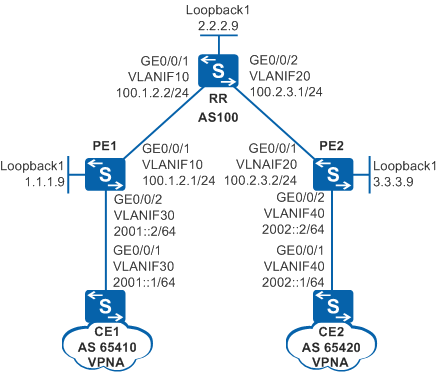
As shown in Figure 1, PE1, PE2, and RR are located in AS100 on the backbone network. CE1 and CE2 belong to VPNA. You need to configure RR as the route reflector of the VPN.
Configuration Roadmap
The configuration roadmap is as follows:
Establish MP-IBGP connections between the PEs and RR. No MP-IBGP connection is required between the PEs.
Establish an EBGP connection between the PEs and CEs.
Establish an MPLS LSP on the public network and enable MPLS LDP on the devices and interfaces along the LSP.
The RR needs to save all VPNv6 routes sent from PE1 and PE2 and advertises the VPNv6 routes to the PEs. Therefore, configure the RR to accept all VPNv6 routing information without filtering the routing information based on VPN targets.
Procedure
- Configure VLANs on interfaces and assign IP addresses to
the VLANIF interfaces and loopback interfaces according to Figure 1.
# Configure PE1.
<HUAWEI> system-view
[HUAWEI] sysname PE1
[PE1] ipv6
[PE1] interface loopback 1
[PE1-LoopBack1] ip address 1.1.1.9 32
[PE1-LoopBack1] quit
[PE1] vlan batch 10 30
[PE1] interface gigabitethernet 0/0/1
[PE1-GigabitEthernet0/0/1] port link-type trunk
[PE1-GigabitEthernet0/0/1] port trunk allow-pass vlan 10
[PE1-GigabitEthernet0/0/1] quit
[PE1] interface gigabitethernet 0/0/2
[PE1-GigabitEthernet0/0/2] port link-type trunk
[PE1-GigabitEthernet0/0/2] port trunk allow-pass vlan 30
[PE1-GigabitEthernet0/0/2] quit
[PE1] interface vlanif 10
[PE1-Vlanif10] ip address 100.1.2.1 24
[PE1-Vlanif10] quit
[PE1] interface vlanif 30
[PE1-Vlanif30] ipv6 enable
[PE1-Vlanif30] ipv6 address 2001::2 64
[PE1-Vlanif30] quit
The configuration on PE2, RR, CE1, and CE2 is similar to the configuration on PE1 and is not mentioned here.
- Configure an IGP protocol on the MPLS backbone network
to implement connectivity between devices along the LSP.
# Configure PE1.
[PE1] ospf
[PE1-ospf-1] area 0
[PE1-ospf-1-area-0.0.0.0] network 1.1.1.9 0.0.0.0
[PE1-ospf-1-area-0.0.0.0] network 100.1.2.0 0.0.0.255
[PE1-ospf-1-area-0.0.0.0] quit
[PE1-ospf-1] quit
The configuration on PE2 and RR is similar to the configuration on PE1 and is not mentioned here.

The IP addresses of loopback interfaces that are used as LSR IDs need to be advertised.
After the configuration is complete, the devices along the LSP can obtain the address of the loopback interface from each other.
The information displayed on PE1 is used as an example.
[PE1] display ip routing-table Route Flags: R - relay, D - download to fib, T - to vpn-instance ------------------------------------------------------------------------------ Routing Tables: Public Destinations : 8 Routes : 8 Destination/Mask Proto Pre Cost Flags NextHop Interface 1.1.1.9/32 Direct 0 0 D 127.0.0.1 LoopBack1 2.2.2.9/32 OSPF 10 1 D 100.1.2.2 Vlanif10 3.3.3.9/32 OSPF 10 2 D 100.1.2.2 Vlanif10 100.1.2.0/24 Direct 0 0 D 100.1.2.1 Vlanif10 100.1.2.1/32 Direct 0 0 D 127.0.0.1 Vlanif10 100.2.3.0/24 OSPF 10 2 D 100.1.2.2 Vlanif10 127.0.0.0/8 Direct 0 0 D 127.0.0.1 InLoopBack0 127.0.0.1/32 Direct 0 0 D 127.0.0.1 InLoopBack0 - Establish LSPs on the MPLS backbone network.
Enable MPLS and MPLS LDP on the devices and interfaces along the LSP.
# Configure PE1.
[PE1] mpls lsr-id 1.1.1.9
[PE1] mpls
[PE1-mpls] quit
[PE1] mpls ldp
[PE1-mpls-ldp] quit
[PE1] interface vlanif 10
[PE1-Vlanif10] mpls
[PE1-Vlanif10] mpls ldp
[PE1-Vlanif10] quit
The configuration on PE2 and RR is similar to the configuration on PE1 and is not mentioned here.
After the configuration is complete, run the display mpls ldp session command on the PEs and RR. The Status field in the command output displays as Operational.
The information displayed on PE1 and RR is used as an example.
[PE1] display mpls ldp session LDP Session(s) in Public Network Codes: LAM(Label Advertisement Mode), SsnAge Unit(DDDD:HH:MM) A '*' before a session means the session is being deleted. ------------------------------------------------------------------------------ PeerID Status LAM SsnRole SsnAge KASent/Rcv ------------------------------------------------------------------------------ 2.2.2.9:0 Operational DU Active 0000:09:23 2253/2237 ------------------------------------------------------------------------------ TOTAL: 1 session(s) Found. [RR] display mpls ldp session LDP Session(s) in Public Network Codes: LAM(Label Advertisement Mode), SsnAge Unit(DDDD:HH:MM) A '*' before a session means the session is being deleted. ---------------------------------------------------------------------- PeerID Status LAM SsnRole SsnAge KASent/Rcv ---------------------------------------------------------------------- 1.1.1.9:0 Operational DU Active 000:00:02 11/11 3.3.3.9:0 Operational DU Passive 000:00:01 8/8 ---------------------------------------------------------------------- TOTAL: 2 session(s) Found. - Configure IPv6 VPN instances on PEs.
For detailed configuration, see Example for Configuring Basic BGP/MPLS IPv6 VPN.
- Establish EBGP peer relationships between PEs and CEs and
import VPN routes into BGP.
For detailed configuration, see Example for Configuring Hub and Spoke (Using BGP4+ Between the PE and CE).
- Establish MP-IBGP peer relationships between PEs and RR.
# Configure PE1.
[PE1] bgp 100
[PE1-bgp] peer 2.2.2.9 as-number 100
[PE1-bgp] peer 2.2.2.9 connect-interface loopback 1
[PE1-bgp] ipv6-family vpnv6
[PE1-bgp-af-vpnv6] peer 2.2.2.9 enable
[PE1-bgp-af-vpnv6] quit
# Configure the RR.
[RR] bgp 100
[RR-bgp] peer 1.1.1.9 as-number 100
[RR-bgp] peer 1.1.1.9 connect-interface loopback 1
[RR-bgp] peer 3.3.3.9 as-number 100
[RR-bgp] peer 3.3.3.9 connect-interface loopback 1
[RR-bgp] ipv6-family vpnv6
[RR-bgp-af-vpnv6] peer 1.1.1.9 enable
[RR-bgp-af-vpnv6] peer 3.3.3.9 enable
[RR-bgp-af-vpnv6] quit
[RR-bgp] quit
# Configure PE2.
The configuration on PE2 is similar to the configuration on PE1 and is not mentioned here.
After the configuration is complete, run the display bgp vpnv6 all peer command on the PEs, and you can see that IBGP peer relationships have been established between the PEs and RR and are in Established state. EBGP peer relationships have been established between the PE and CEs.
The information displayed on PE1 is used as an example.
[PE1] display bgp vpnv6 all peer

 BGP local router ID : 1.1.1.9
 Local AS number : 100
 Total number of peers : 2                 Peers in established state : 2

  Peer            V    AS  MsgRcvd  MsgSent  OutQ  Up/Down       State PrefRcv

  2.2.2.9         4   100       15       17     0 00:13:11 Established       0

  Peer of IPv6-family for vpn instance :

  VPN-Instance VPNA :
  2001::1         4 65410        9       10     0 00:06:41 Established       0
- Enable the route reflection function on the RR.
# Configure the RR.
[RR] bgp 100
[RR-bgp] ipv6-family vpnv6
[RR-bgp-af-vpnv6] peer 1.1.1.9 reflect-client
[RR-bgp-af-vpnv6] peer 3.3.3.9 reflect-client
[RR-bgp-af-vpnv6] undo policy vpn-target
[RR-bgp-af-vpnv6] quit
[RR-bgp] quit
- Verify the configuration.
Check the VPN routing table on a PE. The routing table contains a route to the remote CE.
[PE1] display ipv6 routing-table vpn-instance VPNA
Routing Table : VPNA
         Destinations : 4        Routes : 4

 Destination  : 2001::                          PrefixLength : 64
 NextHop      : 2001::2                         Preference   : 0
 Cost         : 0                               Protocol     : Direct
 RelayNextHop : ::                              TunnelID     : 0x0
 Interface    : Vlanif30                        Flags        : D

 Destination  : 2001::2                         PrefixLength : 128
 NextHop      : ::1                             Preference   : 0
 Cost         : 0                               Protocol     : Direct
 RelayNextHop : ::                              TunnelID     : 0x0
 Interface    : Vlanif30                        Flags        : D

 Destination  : 2002::                          PrefixLength : 64
 NextHop      : ::FFFF:3.3.3.9                  Preference   : 255
 Cost         : 0                               Protocol     : IBGP
 RelayNextHop : ::FFFF:100.1.2.2                TunnelID     : 0xa0010080
 Interface    : Vlanif10                        Flags        : RD

 Destination  : FE80::                          PrefixLength : 10
 NextHop      : ::                              Preference   : 0
 Cost         : 0                               Protocol     : Direct
 RelayNextHop : ::                              TunnelID     : 0x0
 Interface    : NULL0                           Flags        : D
If CE1 and CE2 can ping each other, the route reflection function has been configured successfully.
Configuration Files
PE1 configuration file
#
 sysname PE1
#
 ipv6
#
 vlan batch 10 30
#
ip vpn-instance VPNA
 ipv6-family
  route-distinguisher 100:1
  vpn-target 1:1 export-extcommunity
  vpn-target 1:1 import-extcommunity
#
mpls lsr-id 1.1.1.9
mpls
#
mpls ldp
#
interface Vlanif10
 ip address 100.1.2.1 255.255.255.0
 mpls
 mpls ldp
#
interface Vlanif30
 ipv6 enable
 ip binding vpn-instance VPNA
 ipv6 address 2001::2/64
#
interface GigabitEthernet0/0/1
 port link-type trunk
 port trunk allow-pass vlan 10
#
interface GigabitEthernet0/0/2
 port link-type trunk
 port trunk allow-pass vlan 30
#
interface LoopBack1
 ip address 1.1.1.9 255.255.255.255
#
bgp 100
 router-id 1.1.1.9
 peer 2.2.2.9 as-number 100
 peer 2.2.2.9 connect-interface LoopBack1
 #
 ipv4-family unicast
  undo synchronization
  peer 2.2.2.9 enable
 #
 ipv6-family vpnv6
  policy vpn-target
  peer 2.2.2.9 enable
 #
 ipv6-family vpn-instance VPNA
  peer 2001::1 as-number 65410
  import-route direct
#
ospf 1
 area 0.0.0.0
  network 1.1.1.9 0.0.0.0
  network 100.1.2.0 0.0.0.255
#
return
RR configuration file
#
 sysname RR
#
 ipv6
#
 vlan batch 10 20
#
mpls lsr-id 2.2.2.9
mpls
#
mpls ldp
#
interface Vlanif10
 ip address 100.1.2.2 255.255.255.0
 mpls
 mpls ldp
#
interface Vlanif20
 ip address 100.2.3.1 255.255.255.0
 mpls
 mpls ldp
#
interface GigabitEthernet0/0/1
 port link-type trunk
 port trunk allow-pass vlan 10
#
interface GigabitEthernet0/0/2
 port link-type trunk
 port trunk allow-pass vlan 20
#
interface LoopBack1
 ip address 2.2.2.9 255.255.255.255
#
bgp 100
 router-id 2.2.2.9
 peer 1.1.1.9 as-number 100
 peer 3.3.3.9 as-number 100
 peer 1.1.1.9 connect-interface LoopBack1
 peer 3.3.3.9 connect-interface LoopBack1
 #
 ipv4-family unicast
  undo synchronization
  peer 1.1.1.9 enable
  peer 3.3.3.9 enable
 #
 ipv6-family vpnv6
  reflector cluster-id 100
  undo policy vpn-target
  peer 1.1.1.9 enable
  peer 1.1.1.9 reflect-client
  peer 3.3.3.9 enable
  peer 3.3.3.9 reflect-client
#
ospf 1
 area 0.0.0.0
  network 100.1.2.0 0.0.0.255
  network 100.2.3.0 0.0.0.255
  network 2.2.2.9 0.0.0.0
#
return
PE2 configuration file
#
sysname PE2
#
 ipv6
#
 vlan batch 20 40
#
ip vpn-instance VPNA
 ipv6-family
  route-distinguisher 100:1
  vpn-target 1:1 export-extcommunity
  vpn-target 1:1 import-extcommunity
#
mpls lsr-id 3.3.3.9
mpls
#
mpls ldp
#
interface Vlanif20
 ip address 100.2.3.2 255.255.255.0
 mpls
 mpls ldp
#
interface Vlanif40
 ipv6 enable
 ip binding vpn-instance VPNA
 ipv6 address 2002::2/64
#
interface GigabitEthernet0/0/1
 port link-type trunk
 port trunk allow-pass vlan 20
#
interface GigabitEthernet0/0/2
 port link-type trunk
 port trunk allow-pass vlan 40
#
interface LoopBack1
 ip address 3.3.3.9 255.255.255.255
#
bgp 100
 router-id 3.3.3.9
 peer 2.2.2.9 as-number 100
 peer 2.2.2.9 connect-interface LoopBack1
 #
 ipv4-family unicast
  undo synchronization
  peer 2.2.2.9 enable
 #
 ipv6-family vpnv6
  policy vpn-target
  peer 2.2.2.9 enable
 #
 ipv6-family vpn-instance VPNA
  peer 2002::1 as-number 65420
  import-route direct
#
ospf 1
 area 0.0.0.0
  network 3.3.3.9 0.0.0.0
  network 100.2.3.0 0.0.0.255
#
return
CE1 configuration file
#
 sysname CE1
#
 ipv6
#
 vlan batch 30
#
interface Vlanif30
 ipv6 enable
 ipv6 address 2001::1/64
#
interface GigabitEthernet0/0/1
 port link-type trunk
 port trunk allow-pass vlan 30
#
bgp 65410
 router-id 10.10.10.10
 peer 2001::2 as-number 100
 #
 ipv6-family unicast
  undo synchronization
  peer 2001::2 enable
  import-route direct
#
return
CE2 configuration file
#
 sysname CE2
#
 ipv6
#
 vlan batch 40
#
interface Vlanif40
 ipv6 enable
 ipv6 address 2002::1/64
#
interface GigabitEthernet0/0/1
 port link-type trunk
 port trunk allow-pass vlan 40
#
bgp 65420
 router-id 20.20.20.20
 peer 2002::2 as-number 100
 #
 ipv6-family unicast
  undo synchronization
  peer 2002::2 enable
  import-route direct
#
return