Example for Configuring Manual LDP FRR
Networking Requirements
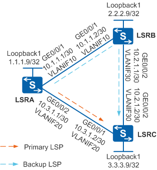
As shown in Figure 1, the network topology is simple and stable, and LSRA, LSRB, and LSRC are MPLS backbone network devices. Two LSPs are set up between LSRA and LSRC to transmit services: primary LSP (LSRA -> LSRC) and backup LSP (LSRA -> LSRB -> PEC). When the primary LSP becomes faulty, traffic is switched to the backup LSP, causing MPLS traffic loss. Short-time interruption of delay-sensitive services such as VoIP, online game, and online video service is unacceptable. It is required that services be fast switched to the backup LSP when the primary LSP becomes faulty, minimizing packet loss.

In this scenario, to avoid loops, ensure that all connected interfaces have STP disabled and connected interfaces are removed from VLAN 1. If STP is enabled and VLANIF interfaces of switches are used to construct a Layer 3 ring network, an interface on the network will be blocked. As a result, Layer 3 services on the network cannot run normally.
Configuration Roadmap
To meet the preceding requirements, configure manual LDP FRR. The configuration roadmap is as follows:
- Configure OSPF on LSRs to implement IP connectivity on the backbone network.
- Configure local LDP sessions on LSRs so that LDP LSPs can be set up to transmit network services.
- Configure static BFD for LDP LSPs on LSRA and LSRC to fast detect faults on LDP LSPs.
- Configure manual LDP FRR on LSRA to minimize packet loss during the active/standby switchover.
On a network where manual LDP FRR is enabled, the backup LSP must be in liberal state. When you run the display ip routing-table ip-address verbose command on an LSR that is enabled with FRR, the command output shows that the status of the backup LSP route is Inactive Adv.
Procedure
- On the switches, create VLANs and VLANIF interfaces, configure IP addresses for the VLANIF interfaces, and add physical interfaces to VLANs.
# Configure LSRA. The configurations of LSRB and LSRC are similar to that of LSRA, and are not mentioned here.
<HUAWEI> system-view
[HUAWEI] sysname LSRA
[LSRA] interface loopback 1
[LSRA-LoopBack1] ip address 1.1.1.9 32
[LSRA-LoopBack1] quit
[LSRA] vlan batch 10 20
[LSRA] interface vlanif 10
[LSRA-Vlanif10] ip address 10.1.1.1 30
[LSRA-Vlanif10] quit
[LSRA] interface vlanif 20
[LSRA-Vlanif20] ip address 10.3.1.1 30
[LSRA-Vlanif20] quit
[LSRA] interface gigabitethernet 0/0/1
[LSRA-GigabitEthernet0/0/1] port link-type trunk
[LSRA-GigabitEthernet0/0/1] port trunk allow-pass vlan 10
[LSRA-GigabitEthernet0/0/1] quit
[LSRA] interface gigabitethernet 0/0/2
[LSRA-GigabitEthernet0/0/2] port link-type trunk
[LSRA-GigabitEthernet0/0/2] port trunk allow-pass vlan 20
[LSRA-GigabitEthernet0/0/2] quit
- Configure OSPF to advertise the network segments connecting to interfaces on each node and to advertise the routes of hosts with LSR IDs.
# Configure LSRA. The configurations of LSRB and LSRC are similar to that of LSRA, and are not mentioned here.
[LSRA] ospf 1
[LSRA-ospf-1] area 0
[LSRA-ospf-1-area-0.0.0.0] network 1.1.1.9 0.0.0.0
[LSRA-ospf-1-area-0.0.0.0] network 10.1.1.0 0.0.0.3
[LSRA-ospf-1-area-0.0.0.0] network 10.3.1.0 0.0.0.3
[LSRA-ospf-1-area-0.0.0.0] quit
[LSRA-ospf-1] quit
After the configuration is complete, run the display ip routing-table command on each node. The command output shows that the nodes have learned routes from each other.
- Enable MPLS and MPLS LDP on each node globally and on the interfaces.
# Configure LSRA. The configurations of LSRB and LSRC are similar to that of LSRA, and are not mentioned here.
[LSRA] mpls lsr-id 1.1.1.9
[LSRA] mpls
[LSRA-mpls] quit
[LSRA] mpls ldp
[LSRA-mpls-ldp] quit
[LSRA] interface vlanif 10
[LSRA-Vlanif10] mpls
[LSRA-Vlanif10] mpls ldp
[LSRA-Vlanif10] quit
[LSRA] interface vlanif 20
[LSRA-Vlanif20] mpls
[LSRA-Vlanif20] mpls ldp
[LSRA-Vlanif20] quit
After the configuration is complete, LDP sessions are established between neighboring nodes. Run the display mpls ldp session command on each node. The command output shows that the LDP session status is Operational. LSRA is used as an example.
[LSRA] display mpls ldp session

 LDP Session(s) in Public Network
 Codes: LAM(Label Advertisement Mode), SsnAge Unit(DDDD:HH:MM)
 A '*' before a session means the session is being deleted.
 ------------------------------------------------------------------------------
 PeerID             Status      LAM  SsnRole  SsnAge      KASent/Rcv
 ------------------------------------------------------------------------------
 2.2.2.9:0          Operational DU   Passive  0000:00:01  8/8
 3.3.3.9:0          Operational DU   Passive  0000:00:01  6/6
 ------------------------------------------------------------------------------
 TOTAL: 2 session(s) Found.
- Configure static BFD for LDP LSPs on LSRA and LSRC.
# Configure LSRA.
[LSRA] bfd
[LSRA-bfd] quit
[LSRA] bfd lsratoc bind ldp-lsp peer-ip 3.3.3.9 nexthop 10.3.1.2 interface vlanif 20
[LSRA-bfd-lsp-session-lsratoc] discriminator local 1
[LSRA-bfd-lsp-session-lsratoc] discriminator remote 2
[LSRA-bfd-lsp-session-lsratoc] min-tx-interval 100
[LSRA-bfd-lsp-session-lsratoc] min-rx-interval 100
[LSRA-bfd-lsp-session-lsratoc] process-pst
[LSRA-bfd-lsp-session-lsratoc] commit
[LSRA-bfd-lsp-session-lsratoc] quit
# Configure LSRC.
[LSRC] bfd
[LSRC-bfd] quit
[LSRC] bfd lsrctoa bind  peer-ip 1.1.1.9
[LSRC-bfd-session-lsrctoa] discriminator local 2
[LSRC-bfd-session-lsrctoa] discriminator remote 1
[LSRC-bfd-session-lsrctoa] min-tx-interval 100
[LSRC-bfd-session-lsrctoa] min-rx-interval 100
[LSRC-bfd-session-lsrctoa] commit
[LSRC-bfd-session-lsrctoa] quit
After the configuration is complete, run the display bfd session all command on LSRA. You can see that the value of the State field is Up.
- Enable manual LDP FRR on VLANIF 20 of LSRA, and specify the next hop address used to create the backup LSP.
# Configure LSRA.
[LSRA] interface vlanif 20
[LSRA-Vlanif20] mpls ldp frr nexthop 10.1.1.2
[LSRA-Vlanif20] quit
- Verify the configuration.
Run the display mpls lsp command on LSRA. The command output shows that manual LDP FRR is enabled on the LSP of LSRC.
[LSRA] display mpls lsp

Flag after Out IF: (I) - LSP Is Only Iterated by RLFA
 -------------------------------------------------------------------------------
                  LSP Information: LDP LSP
 -------------------------------------------------------------------------------
 FEC                In/Out Label  In/Out IF                      Vrf Name
 1.1.1.9/32         3/NULL        -/-
 2.2.2.9/32         NULL/3        -/Vlanif10
 2.2.2.9/32         1024/3        -/Vlanif10
 3.3.3.9/32         NULL/3        -/Vlanif20
    **LDP FRR**         /1025      /Vlanif10
 3.3.3.9/32         1025/3        -/Vlanif20
    **LDP FRR**         /1025      /Vlanif10
Connect two interfaces, Port 1 and Port 2 on a tester, to LSRA and LSRC respectively. On Port 1, inject MPLS traffic and send traffic to Port 2. Run the shutdown command on VLANIF 20 of LSRA to simulate a fault on the primary LSP. You can see that traffic is fast switched to the backup LSP.
Configuration Files
LSRA configuration file
#
sysname LSRA
#
vlan batch 10 20
#
bfd
#
mpls lsr-id 1.1.1.9
mpls
#
mpls ldp
#
interface Vlanif10
 ip address 10.1.1.1 255.255.255.252
 mpls
 mpls ldp
#
interface Vlanif20
 ip address 10.3.1.1 255.255.255.252
 mpls
 mpls ldp
 mpls ldp frr nexthop 10.1.1.2
#
interface GigabitEthernet0/0/1
 port link-type trunk
 port trunk allow-pass vlan 10
#
interface GigabitEthernet0/0/2
 port link-type trunk
 port trunk allow-pass vlan 20
#
interface LoopBack1
 ip address 1.1.1.9 255.255.255.255
#
ospf 1
 area 0.0.0.0
  network 1.1.1.9 0.0.0.0
  network 10.1.1.0 0.0.0.3
  network 10.3.1.0 0.0.0.3
#
bfd lsratoc bind ldp-lsp peer-ip 3.3.3.9 nexthop 10.3.1.2 interface Vlanif20
 discriminator local 1
 discriminator remote 2
 min-tx-interval 100
 min-rx-interval 100
 process-pst
 commit
#
return
LSRB configuration file
#
sysname LSRB
#
vlan batch 10 30
#
mpls lsr-id 2.2.2.9
mpls
#
mpls ldp
#
interface Vlanif10
 ip address 10.1.1.2 255.255.255.252
 mpls
 mpls ldp
#
interface Vlanif30
 ip address 10.2.1.1 255.255.255.252
 mpls
 mpls ldp
#
interface GigabitEthernet0/0/1
 port link-type trunk
 port trunk allow-pass vlan 10
#
interface GigabitEthernet0/0/2
 port link-type trunk
 port trunk allow-pass vlan 30
#
interface LoopBack1
 ip address 2.2.2.9 255.255.255.255
#
ospf 1
 area 0.0.0.0
  network 2.2.2.9 0.0.0.0
  network 10.1.1.0 0.0.0.3
  network 10.2.1.0 0.0.0.3
#
return
LSRC configuration file
#
sysname LSRC
#
vlan batch 20 30
#
bfd
#
mpls lsr-id 3.3.3.9
mpls
#
mpls ldp
#
interface Vlanif20
 ip address 10.3.1.2 255.255.255.252
 mpls
 mpls ldp
#
interface Vlanif30
 ip address 10.2.1.2 255.255.255.252
 mpls
 mpls ldp
#
interface GigabitEthernet0/0/1
 port link-type trunk
 port trunk allow-pass vlan 20
#
interface GigabitEthernet0/0/2
 port link-type trunk
 port trunk allow-pass vlan 30
#
interface LoopBack1
 ip address 3.3.3.9 255.255.255.255
#
bfd lsrctoa bind peer-ip 1.1.1.9
 discriminator local 2
 discriminator remote 1
 min-tx-interval 100
 min-rx-interval 100
 commit
#
ospf 1
 area 0.0.0.0
  network 3.3.3.9 0.0.0.0
  network 10.2.1.0 0.0.0.3
  network 10.3.1.0 0.0.0.3
#
return