Example for Configuring Auto LDP FRR
Networking Requirements
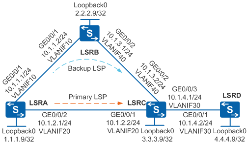
As shown in Figure 1, the network topology is complex and unstable, and LSRA, LSRB, LSRC, and LSRD are MPLS backbone network devices. Two LSPs are set up between LSRA and LSRC to transmit services: primary LSP (LSRA -> LSRC) and backup LSP (LSRA -> LSRB -> LSRC). When the primary LSP becomes faulty, traffic is switched to the backup LSP, causing MPLS traffic loss. Short-time interruption of delay-sensitive services such as VoIP, online game, and online video service is unacceptable. It is required that services be fast switched to the backup LSP when the primary LSP becomes faulty, minimizing packet loss.

In this scenario, to avoid loops, ensure that all connected interfaces have STP disabled and connected interfaces are removed from VLAN 1. If STP is enabled and VLANIF interfaces of switches are used to construct a Layer 3 ring network, an interface on the network will be blocked. As a result, Layer 3 services on the network cannot run normally.
Configuration Roadmap
To meet the preceding requirements, configure Auto LDP FRR. The configuration roadmap is as follows:
- Configure IS-IS on LSRs to implement IP connectivity on the backbone network.
- Configure local LDP sessions on LSRs so that LDP LSPs can be set up to transmit network services.
- Configure dynamic BFD for LDP LSPs on LSRA and LSRC to fast detect faults on LDP LSPs.
- Configure Auto LDP FRR on LSRA to minimize packet loss during the active/standby switchover.
Procedure
- On the switches, create VLANs and VLANIF interfaces, configure IP addresses for the VLANIF interfaces, and add physical interfaces to VLANs.
# Configure LSRA. The configurations of LSRB, LSRC, and LSRD are similar to the configuration of LSRA, and are not mentioned here.
<HUAWEI> system-view
[HUAWEI] sysname LSRA
[LSRA] interface loopback 0
[LSRA-LoopBack0] ip address 1.1.1.9 32
[LSRA-LoopBack0] quit
[LSRA] vlan batch 10 20
[LSRA] interface vlanif 10
[LSRA-Vlanif10] ip address 10.1.1.1 24
[LSRA-Vlanif10] quit
[LSRA] interface vlanif 20
[LSRA-Vlanif20] ip address 10.1.2.1 24
[LSRA-Vlanif20] quit
[LSRA] interface gigabitethernet 0/0/1
[LSRA-GigabitEthernet0/0/1] port link-type trunk
[LSRA-GigabitEthernet0/0/1] port trunk allow-pass vlan 10
[LSRA-GigabitEthernet0/0/1] quit
[LSRA] interface gigabitethernet 0/0/2
[LSRA-GigabitEthernet0/0/2] port link-type trunk
[LSRA-GigabitEthernet0/0/2] port trunk allow-pass vlan 20
[LSRA-GigabitEthernet0/0/2] quit
- Configure IS-IS to advertise the network segments connecting to interfaces on each node and to advertise the routes of hosts with LSR IDs.
# Configure LSRA.
[LSRA] isis 1
[LSRA-isis-1] network-entity 10.0000.0000.0001.00
[LSRA-isis-1] quit
[LSRA] interface vlanif 10
[LSRA-Vlanif10] isis enable 1
[LSRA-Vlanif10] quit
[LSRA] interface vlanif 20
[LSRA-Vlanif20] isis enable 1
[LSRA-Vlanif20] quit
[LSRA] interface loopback 0
[LSRA-LoopBack0] isis enable 1
[LSRA-LoopBack0] quit
# Configure LSRB.
[LSRB] isis 1
[LSRB-isis-1] network-entity 10.0000.0000.0002.00
[LSRB-isis-1] quit
[LSRB] interface vlanif 10
[LSRB-Vlanif10] isis enable 1
[LSRB-Vlanif10] quit
[LSRB] interface vlanif 40
[LSRB-Vlanif40] isis enable 1
[LSRB-Vlanif40] quit
[LSRB] interface loopback 0
[LSRB-LoopBack0] isis enable 1
[LSRB-LoopBack0] quit
# Configure LSRC.
[LSRC] isis 1
[LSRC-isis-1] network-entity 10.0000.0000.0003.00
[LSRC-isis-1] quit
[LSRC] interface vlanif 30
[LSRC-Vlanif30] isis enable 1
[LSRC-Vlanif30] quit
[LSRC] interface vlanif 20
[LSRC-Vlanif20] isis enable 1
[LSRC-Vlanif20] quit
[LSRC] interface vlanif 40
[LSRC-Vlanif40] isis enable 1
[LSRC-Vlanif40] quit
[LSRC] interface loopback 0
[LSRC-LoopBack0] isis enable 1
[LSRC-LoopBack0] quit
# Configure LSRD.
[LSRD] isis 1
[LSRD-isis-1] network-entity 10.0000.0000.0004.00
[LSRD-isis-1] quit
[LSRD] interface vlanif 30
[LSRD-Vlanif30] isis enable 1
[LSRD-Vlanif30] quit
[LSRD] interface loopback 0
[LSRD-LoopBack0] isis enable 1
[LSRD-LoopBack0] quit
- Configure global and interface-based MPLS and MPLS LDP on each node so that the network can forward MPLS traffic. Then check the LSP setup result.
# Configure LSRA. The configurations of LSRB, LSRC, and LSRD are similar to the configuration of LSRA, and are not mentioned here.
[LSRA] mpls lsr-id 1.1.1.9
[LSRA] mpls
[LSRA-mpls] quit
[LSRA] mpls ldp
[LSRA-mpls-ldp] quit
[LSRA] interface vlanif 10
[LSRA-Vlanif10] mpls
[LSRA-Vlanif10] mpls ldp
[LSRA-Vlanif10] quit
[LSRA] interface vlanif 20
[LSRA-Vlanif20] mpls
[LSRA-Vlanif20] mpls ldp
[LSRA-Vlanif20] quit
# After the configuration is complete, run the display mpls lsp command on LSRA to view the established LSP.
[LSRA] display mpls lsp

Flag after Out IF: (I) - LSP Is Only Iterated by RLFA
-------------------------------------------------------------------------------
                 LSP Information: LDP LSP
-------------------------------------------------------------------------------
FEC                In/Out Label  In/Out IF                      Vrf Name
1.1.1.9/32         3/NULL        -/-
2.2.2.9/32         NULL/3        -/Vlanif10
2.2.2.9/32         1024/3        -/Vlanif10
3.3.3.9/32         NULL/3        -/Vlanif20
3.3.3.9/32         1025/3        -/Vlanif20
4.4.4.9/32         NULL/1026     -/Vlanif20
4.4.4.9/32         1026/1026     -/Vlanif20
The preceding command output shows that by default, the routes with 32-bit addresses trigger the setup of LSPs.
- Configure dynamic BFD to detect connectivity of the LDP LSP between LSRA and LSRC.
# Configure an FEC list on LSRA to ensure that BFD detects only connectivity of the LDP LSP between LSRA and LSRC.
[LSRA] fec-list tortc
[LSRA-fec-list-tortc] fec-node 3.3.3.9
[LSRA-fec-list-tortc] quit
# Enable BFD on LSRA, specify the FEC list that triggers a BFD session dynamically, and adjust BFD parameters.
[LSRA] bfd
[LSRA-bfd] quit
[LSRA] mpls
[LSRA-mpls] mpls bfd-trigger fec-list tortc
[LSRA-mpls] mpls bfd enable
[LSRA-mpls] mpls bfd min-tx-interval 100 min-rx-interval 100
[LSRA-mpls] quit
# Enable the capability to passively create BFD sessions on LSRC.
[LSRC] bfd
[LSRC-bfd] mpls-passive
[LSRC-bfd] quit
After the configuration is complete, view the BFD session status on LSRA. You can see that the value of the State field is Up.
- Enable IS-IS auto FRR on LSRA. View the routing information and the setup of the backup LSP.
# Enable IS-IS auto FRR on LSRA.
[LSRA] isis
[LSRA-isis-1] frr
[LSRA-isis-1-frr] loop-free-alternate
[LSRA-isis-1-frr] quit
[LSRA-isis-1] quit
# Display information about the direct routes between LSRA and LSRC, and between LSRA and LSRD.
[LSRA] display ip routing-table 10.1.4.0 verbose
Route Flags: R - relay, D - download to fib, T - to vpn-instance
------------------------------------------------------------------------------
Routing Table : Public
Summary Count : 1

Destination: 10.1.4.0/24
     Protocol: ISIS-L1         Process ID: 1
   Preference: 15                    Cost: 20
      NextHop: 10.1.2.2         Neighbour: 0.0.0.0
        State: Active Adv             Age: 00h05m38s
          Tag: 0                 Priority: medium
        Label: NULL               QoSInfo: 0x0
   IndirectID: 0x0
 RelayNextHop: 0.0.0.0          Interface: Vlanif20
     TunnelID: 0x0                  Flags: D
    BkNextHop: 10.1.1.2       BkInterface: Vlanif10
      BkLabel: NULL           SecTunnelID: 0x0
 BkPETunnelID: 0x0        BkPESecTunnelID: 0x0
 BkIndirectID: 0x0
The preceding command output shows that a backup IS-IS route is generated after IS-IS auto FRR is enabled.
# Run the display mpls lsp command on LSRA to view the LSP setup result.
[LSRA] display mpls lsp

Flag after Out IF: (I) - LSP Is Only Iterated by RLFA
-------------------------------------------------------------------------------
                 LSP Information: LDP LSP
-------------------------------------------------------------------------------
FEC                In/Out Label  In/Out IF                      Vrf Name
1.1.1.9/32         3/NULL        -/-
2.2.2.9/32         NULL/3        -/Vlanif10
   **LDP FRR**         /1025      /Vlanif20
2.2.2.9/32         1024/3        -/Vlanif10
   **LDP FRR**         /1025      /Vlanif20
3.3.3.9/32         NULL/3        -/Vlanif20
   **LDP FRR**         /1025      /Vlanif10
3.3.3.9/32         1025/3        -/Vlanif20
   **LDP FRR**         /1025      /Vlanif10
4.4.4.9/32         NULL/1026     -/Vlanif20
   **LDP FRR**         /1026      /Vlanif10
4.4.4.9/32         1026/1026     -/Vlanif20
   **LDP FRR**         /1026      /Vlanif10
The preceding command output shows that by default, the routes with 32-bit addresses trigger the setup of a backup LSP.
- Run the lsp-trigger command on LSRC to change the LSP triggering policy so that all routes trigger the setup of LSPs. Then check the LSP setup result.
# Run the lsp-trigger command on LSRC to change the LSP triggering policy so that all routes trigger the setup of LSPs.
[LSRC] mpls
[LSRC-mpls] lsp-trigger all
[LSRC-mpls] quit
# Run the display mpls lsp command on LSRA to view the established LSPs.
[LSRA] display mpls lsp

Flag after Out IF: (I) - LSP Is Only Iterated by RLFA
-------------------------------------------------------------------------------
                 LSP Information: LDP LSP
-------------------------------------------------------------------------------
FEC                In/Out Label  In/Out IF                      Vrf Name
1.1.1.9/32         3/NULL        -/-
2.2.2.9/32         NULL/3        -/Vlanif10
   **LDP FRR**         /1025      /Vlanif20
2.2.2.9/32         1024/3        -/Vlanif10
   **LDP FRR**         /1025      /Vlanif20
3.3.3.9/32         NULL/3        -/Vlanif20
   **LDP FRR**         /1025      /Vlanif10
3.3.3.9/32         1025/3        -/Vlanif20
   **LDP FRR**         /1025      /Vlanif10
4.4.4.9/32         NULL/1026     -/Vlanif20
   **LDP FRR**         /1026      /Vlanif10
4.4.4.9/32         1026/1026     -/Vlanif20
   **LDP FRR**         /1026      /Vlanif10
10.1.3.0/24        1027/3        -/Vlanif20
10.1.4.0/24        1028/3        -/Vlanif20
The preceding command output shows that the routes with 24-bit addresses trigger the setup of LSPs.
- Configure a triggering policy to specify that all backup routes trigger the setup of backup LSPs.
# Run the auto-frr lsp-trigger command on LSRA so that all backup routes trigger the setup of backup LSPs.
[LSRA] mpls ldp
[LSRA-mpls-ldp] auto-frr lsp-trigger all
[LSRA-mpls-ldp] quit
- Verify the configuration.
Run the display mpls lsp command on LSRA to view the setup of backup LSPs.
[LSRA] display mpls lsp

Flag after Out IF: (I) - LSP Is Only Iterated by RLFA
-------------------------------------------------------------------------------
                 LSP Information: LDP LSP
-------------------------------------------------------------------------------
FEC                In/Out Label  In/Out IF                      Vrf Name
1.1.1.9/32         3/NULL        -/-
2.2.2.9/32         NULL/3        -/Vlanif10
   **LDP FRR**         /1025      /Vlanif20
2.2.2.9/32         1024/3        -/Vlanif10
   **LDP FRR**         /1025      /Vlanif20
3.3.3.9/32         NULL/3        -/Vlanif20
   **LDP FRR**         /1025      /Vlanif10
3.3.3.9/32         1025/3        -/Vlanif20
   **LDP FRR**         /1025      /Vlanif10
4.4.4.9/32         NULL/1026     -/Vlanif20
   **LDP FRR**         /1026      /Vlanif10
4.4.4.9/32         1026/1026     -/Vlanif20
   **LDP FRR**         /1026      /Vlanif10
10.1.3.0/24        1027/3        -/Vlanif20
10.1.4.0/24        1028/3        -/Vlanif20
   **LDP FRR**         /1027      /Vlanif10
The preceding command output shows that the routes with 24-bit addresses trigger the setup of LSPs.
Connect two interfaces, Port 1 and Port 2 on a tester, to LSRA and LSRD respectively. On Port 1, inject MPLS traffic and send traffic to Port 2. Run the shutdown command on VLANIF 20 of LSRA to simulate a fault on the primary LSP. You can see that traffic is fast switched to the backup LSP.
Configuration Files
LSRA configuration file
#
sysname LSRA
#
vlan batch 10 20
#
bfd
#
mpls lsr-id 1.1.1.9
mpls
 mpls bfd enable
 mpls bfd-trigger fec-list tortc
 mpls bfd min-tx-interval 100 min-rx-interval 100
#
fec-list tortc
 fec-node 3.3.3.9
#
mpls ldp
 auto-frr lsp-trigger all
#
isis 1
 network-entity 10.0000.0000.0001.00
 frr
  loop-free-alternate level-1
  loop-free-alternate level-2
#
interface Vlanif10
 ip address 10.1.1.1 255.255.255.0
 isis enable 1
 mpls
 mpls ldp
#
interface Vlanif20
 ip address 10.1.2.1 255.255.255.0
 isis enable 1
 mpls
 mpls ldp
#
interface GigabitEthernet0/0/1
 port link-type trunk
 port trunk allow-pass vlan 10
#
interface GigabitEthernet0/0/2
 port link-type trunk
 port trunk allow-pass vlan 20
#
interface LoopBack0
 ip address 1.1.1.9 255.255.255.255
 isis enable 1
#
return
LSRB configuration file
#
sysname LSRB
#
vlan batch 10 40
#
mpls lsr-id 2.2.2.9
mpls
#
mpls ldp
#
isis 1
 network-entity 10.0000.0000.0002.00
#
interface Vlanif10
 ip address 10.1.1.2 255.255.255.0
 isis enable 1
 mpls
 mpls ldp
#
interface Vlanif40
 ip address 10.1.3.1 255.255.255.0
 isis enable 1
 mpls
 mpls ldp
#
interface GigabitEthernet0/0/1
 port link-type trunk
 port trunk allow-pass vlan 10
#
interface GigabitEthernet0/0/2
 port link-type trunk
 port trunk allow-pass vlan 40
#
interface LoopBack0
 ip address 2.2.2.9 255.255.255.255
 isis enable 1
#
return
LSRC configuration file
#
sysname LSRC
#
vlan batch 20 30 40
#
bfd
 mpls-passive
#
mpls lsr-id 3.3.3.9
mpls
 lsp-trigger all
#
mpls ldp
#
isis 1
 network-entity 10.0000.0000.0003.00
#
interface Vlanif20
 ip address 10.1.2.2 255.255.255.0
 isis enable 1
 mpls
 mpls ldp
#
interface Vlanif30
 ip address 10.1.4.1 255.255.255.0
 isis enable 1
 mpls
 mpls ldp
#
interface Vlanif40
 ip address 10.1.3.2 255.255.255.0
 isis enable 1
 mpls
 mpls ldp
#
interface GigabitEthernet0/0/1
 port link-type trunk
 port trunk allow-pass vlan 20
#
interface GigabitEthernet0/0/2
 port link-type trunk
 port trunk allow-pass vlan 40
#
interface GigabitEthernet0/0/3
 port link-type trunk
 port trunk allow-pass vlan 30
#
interface LoopBack0
 ip address 3.3.3.9 255.255.255.255
 isis enable 1
#
return
LSRD configuration file
#
sysname LSRD
#
vlan batch 30
#
mpls lsr-id 4.4.4.9
mpls
#
mpls ldp
#
isis 1
 network-entity 10.0000.0000.0004.00
#
interface Vlanif30
 ip address 10.1.4.2 255.255.255.0
 isis enable 1
 mpls
 mpls ldp
#
interface GigabitEthernet0/0/1
 port link-type trunk
 port trunk allow-pass vlan 30
#
interface LoopBack0
 ip address 4.4.4.9 255.255.255.255
 isis enable 1
#
return