Example for Configuring MAC Address-Prioritized Portal Authentication in a Wireless-to-Wired Scenario
Networking Requirements
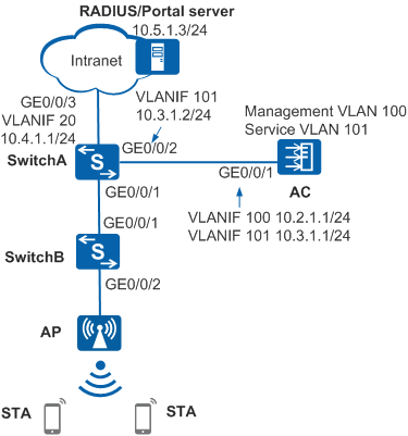
On the network shown in Figure 1, the AC and AP are third-party WLAN access devices. Mobile STAs can access the Internet only after associating with a Wi-Fi network and passing Portal authentication. The requirements are as follows:
- To facilitate network access, MAC address-prioritized Portal authentication is enabled. After passing Portal authentication for the first time, the user can go online and offline freely within a certain period (for example, 60 minutes) without entering the user name and password again.
- Since the AC and AP are non-Huawei devices, MAC address-prioritized Portal authentication is deployed on SwitchA. The AC sends wireless packets to SwitchA for authentication in wired mode. Authentication is not required for the AP, and AP information is not stored on the RADIUS server.
Configuration Precautions
- You are advised to deploy the authentication point on the AC, instead of a switch. This is because the switch cannot detect roaming, login, and logout of STAs, affecting wireless authentication experience.
- When STAs roam between different VLANs, run the authentication mac-move enable command to enable MAC address migration. Otherwise, the STAs will be logged out and need to perform Portal authentication again.
The RADIUS authentication and accounting keys configured on the RADIUS server must be the same as the shared key of the RADIUS server configured on the device.
- The Portal shared key and port number configured on the Portal server must be the same as the shared key configured on the device and the port number used by the device to listen to Portal protocol packets.
- The default outbound interface IP address of the device is used as the source IP address for sending Portal packets to the Portal server. This IP address must be the same as the device IP address configured on the Portal server. You can run the source-interface or source-ip command to change this IP address.
- In this example, Huawei's Agile Controller-Campus (required version: V100R003C60) acts as the RADIUS/Portal server. For details, see the Agile Controller-Campus Product Documentation.
Configuration Roadmap
- Configure network connectivity on switches.
- Configure AAA on SwitchA to implement RADIUS authentication, authorization, and accounting for STAs, and configure non-authentication for the AP.
- Configure MAC address-prioritized Portal authentication on SwitchA to authenticate STAs.
- Configure basic WLAN services on the AC, and configure STAs to access the network in open mode.
- Configure Agile Controller-Campus to implement authentication, authorization, and accounting for STAs.
Procedure
- Configure network connectivity.
# Add GE0/0/1 of SwitchA connected to SwitchB to VLANs 100 and 101. In this example, the AC uses the direct forwarding mode. If the AC uses the tunnel forwarding mode, you do not need to add this interface to VLAN 101.
<HUAWEI> system-view
[HUAWEI] sysname SwitchA
[SwitchA] vlan batch 20 100 101
[SwitchA] interface gigabitethernet 0/0/1
[SwitchA-GigabitEthernet0/0/1] port link-type trunk
[SwitchA-GigabitEthernet0/0/1] port trunk allow-pass vlan 100 101
[SwitchA-GigabitEthernet0/0/1] quit
# Add GE0/0/2 of SwitchA connected to the AC to VLANs 100 and 101.
[SwitchA] interface gigabitethernet 0/0/2
[SwitchA-GigabitEthernet0/0/2] port link-type trunk
[SwitchA-GigabitEthernet0/0/2] port trunk allow-pass vlan 100 101
[SwitchA-GigabitEthernet0/0/2] quit
# Add GE0/0/3 of SwitchA connected to the server to VLAN 20.
[SwitchA] interface gigabitethernet 0/0/3
[SwitchA-GigabitEthernet0/0/3] port link-type trunk
[SwitchA-GigabitEthernet0/0/3] port trunk allow-pass vlan 20
[SwitchA-GigabitEthernet0/0/3] quit
# Add interfaces on SwitchB to VLANs 100 and 101. In this example, the AC uses the direct forwarding mode. If the AC uses the tunnel forwarding mode, you do not need to add this interface to VLAN 101.
<HUAWEI> system-view
[HUAWEI] sysname SwitchB
[SwitchB] vlan batch 100 101
[SwitchB] interface gigabitethernet 0/0/1
[SwitchB-GigabitEthernet0/0/1] port link-type trunk
[SwitchB-GigabitEthernet0/0/1] port trunk allow-pass vlan 100 101
[SwitchB-GigabitEthernet0/0/1] quit
[SwitchB] interface gigabitethernet 0/0/2
[SwitchB-GigabitEthernet0/0/2] port link-type trunk
[SwitchB-GigabitEthernet0/0/2] port trunk allow-pass vlan 100 101
[SwitchB-GigabitEthernet0/0/2] port trunk pvid vlan 100
[SwitchB-GigabitEthernet0/0/2] quit
# On SwitchA, specify an IP address for a VLANIF interface and configure a route destined for the server. In this example, the next hop is 10.4.1.2.
[SwitchA] interface vlanif 20
[SwitchA-Vlanif20] ip address 10.4.1.1 24
[SwitchA-Vlanif20] quit
[SwitchA] interface vlanif 101
[SwitchA-Vlanif101] ip address 10.3.1.2 24
[SwitchA-Vlanif101] quit
[SwitchA] ip route-static 10.5.1.0 255.255.255.0 10.4.1.2
- Configure AAA on SwitchA.
Create and configure a RADIUS server template, an AAA authentication scheme, and an authentication domain.
# Create and configure a RADIUS server template named rd1.[SwitchA] radius-server template rd1 [SwitchA-radius-rd1] radius-server authentication 10.5.1.3 1812 [SwitchA-radius-rd1] radius-server accounting 10.5.1.3 1813 [SwitchA-radius-rd1] radius-server shared-key cipher Huawei@2014 [SwitchA-radius-rd1] quit
# Create an AAA authentication scheme named abc and set the authentication mode to RADIUS.[SwitchA] aaa [SwitchA-aaa] authentication-scheme abc [SwitchA-aaa-authen-abc] authentication-mode radius [SwitchA-aaa-authen-abc] quit
# Configure an accounting scheme named acco1.[SwitchA-aaa] accounting-scheme acco1 [SwitchA-aaa-accounting-acco1] accounting-mode radius [SwitchA-aaa-accounting-acco1] accounting realtime 15 [SwitchA-aaa-accounting-acco1] quit
# Create an authentication domain named isp, and bind the AAA authentication scheme abc, accounting scheme acco1, and RADIUS server template rd1 to the domain.[SwitchA-aaa] domain isp [SwitchA-aaa-domain-isp] authentication-scheme abc [SwitchA-aaa-domain-isp] accounting-scheme acco1 [SwitchA-aaa-domain-isp] radius-server rd1 [SwitchA-aaa-domain-isp] quit [SwitchA-aaa] quit
- Configure non-authentication for the AP.# Create an AAA authentication scheme named noauthen and set the authentication mode to none.
[SwitchA] aaa
[SwitchA-aaa] authentication-scheme noauthen
[SwitchA-aaa-authen-noauthen] authentication-mode none
[SwitchA-aaa-authen-noauthen] quit
# Create an authentication domain for the AP.[SwitchA-aaa] domain ap_noauthen [SwitchA-aaa-domain-ap_noauthen] authentication-scheme noauthen [SwitchA-aaa-domain-ap_noauthen] quit [SwitchA-aaa] quit
# Configure non-authentication for the AP using either of the following methods:
- Specify an AP authentication domain based on the MAC address prefix.
[SwitchA] domain ap_noauthen mac-authen force mac-address 84a9-c48d-4020 mask ffff-ffff-ff00
- Configure the user context identification function.
[SwitchA] access-context profile enable
[SwitchA] access-context profile name ap_access
[SwitchA-access-context-ap_access] if-match vlan-id 100
[SwitchA-access-context-ap_access] quit
[SwitchA] access-author policy name ap_noauthen
[SwitchA-access-author-ap_noauthen] match access-context-profile ap_access action access-domain ap_noauthen
[SwitchA-access-author-ap_noauthen] quit
[SwitchA] access-author policy ap_noauthen global
- Specify an AP authentication domain based on the MAC address prefix.
- Configure MAC address-prioritized Portal authentication on SwitchA.# Change the NAC mode to unified.
[SwitchA] authentication unified-mode

By default, the unified mode is enabled. After you change the NAT mode between common and unified, the device automatically restarts.
# Configure a Portal server template named abc.[SwitchA] web-auth-server abc [SwitchA-web-auth-server-abc] server-ip 10.5.1.3 [SwitchA-web-auth-server-abc] port 50200 [SwitchA-web-auth-server-abc] url http://10.5.1.3:8445/portal [SwitchA-web-auth-server-abc] shared-key cipher Huawei@123 [SwitchA-web-auth-server-abc] quit
# Configure a Portal access profile named web1.
[SwitchA] portal-access-profile name web1
[SwitchA-portal-acces-profile-web1] web-auth-server abc direct
[SwitchA-portal-acces-profile-web1] quit
# Configure a MAC access profile.[SwitchA] mac-access-profile name m1 [SwitchA-mac-access-profile-m1] quit
# Bind the MAC access profile and Portal access profile to the authentication profile p1.[SwitchA] authentication-profile name p1 [SwitchA-authen-profile-p1] mac-access-profile m1 [SwitchA-authen-profile-p1] portal-access-profile web1 [SwitchA-authen-profile-p1] access-domain isp force [SwitchA-authen-profile-p1] quit
# Bind the authentication profile to an interface.[SwitchA] interface gigabitethernet 0/0/1 [SwitchA-GigabitEthernet0/0/1] authentication-profile p1 [SwitchA-GigabitEthernet0/0/1] quit
- Configure the AC.
- On the AC, configure IP addresses for interfaces and a route destined for the RADIUS server.
- Configure the AC as a DHCP server to assign IP addresses to STAs and APs.
- Configure basic wireless services, and enable users to access the network in open mode.
- Configure Agile Controller-Campus.
- Log in to Agile Controller-Campus.
- Choose Resource > User > User Management and click Add to create a common account.
- Choose Resource > Device > Device Management, click Add, and set device parameters, including the SwitchA IP address and RADIUS authentication and accounting parameters.
- Choose System > Terminal Configuration > Global Parameters. Under Configure MAC Address-Prioritized Portal Authentication, enable MAC address-prioritized Portal authentication and set the MAC address validity period to 60 minutes.
- Verify the configuration.
- A user starts a STA and associates the STA with a Wi-Fi network normally. After MAC address authentication fails, the wireless user is redirected to the Portal authentication page and enters the user name and password on this page. After the authentication is successful, the user can access the Internet.
- Run the display access-user ip-address command on SwitchA to check information about the wireless user.