Example for Configuring OSPF Stub Areas
Networking Requirements
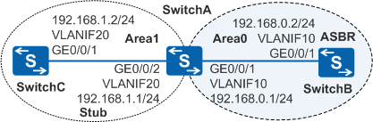
As shown in Figure 1, OSPF is running among three switches, the entire OSPF network is partitioned into Area0 and Area1, and SwitchB functions as an ASBR to communicate with external networks. The size of the OSPF routing table on SwitchC needs to be reduced, which is expected not to affect the communication.
Configuration Roadmap
The configuration roadmap is as follows:
Configure basic OSPF functions on each switch to implement basic connections on the OSPF network.
Configure static routes on SwitchB and import them to the OSPF routing table so that there are reachable routes between the OSPF network and external networks.
Configure Area1 as a stub area to reduce the size of the OSPF routing table on SwitchC.
Disable the ABR (SwitchA) from advertising Type 3 LSAs to Area1 (this configuration indicates that Area 1 is configured as a totally stub area) to further reduce the size of the OSPF routing table on SwitchC.
Procedure
- Configure VLANs for interfaces.
# Configure SwitchA. The configurations of SwitchB and SwitchC are similar to the configuration of SwitchA.
<HUAWEI> system-view
[HUAWEI] sysname SwitchA
[SwitchA] vlan batch 10 20
[SwitchA] interface gigabitethernet 0/0/1
[SwitchA-GigabitEthernet0/0/1] port link-type trunk
[SwitchA-GigabitEthernet0/0/1] port trunk allow-pass vlan 10
[SwitchA-GigabitEthernet0/0/1] quit
[SwitchA] interface gigabitethernet 0/0/2
[SwitchA-GigabitEthernet0/0/2] port link-type trunk
[SwitchA-GigabitEthernet0/0/2] port trunk allow-pass vlan 20
[SwitchA-GigabitEthernet0/0/2] quit
- Configure an IP address for each VLANIF interface.
# Configure SwitchA. The configurations of SwitchB and SwitchC are similar to the configuration of SwitchA.
[SwitchA] interface vlanif 10
[SwitchA-Vlanif10] ip address 192.168.0.1 24
[SwitchA-Vlanif10] quit
[SwitchA] interface vlanif 20
[SwitchA-Vlanif20] ip address 192.168.1.1 24
[SwitchA-Vlanif20] quit
- Configure basic OSPF functions.
# Configure SwitchA.
[SwitchA] ospf 1 router-id 10.1.1.1
[SwitchA-ospf-1] area 0
[SwitchA-ospf-1-area-0.0.0.0] network 192.168.0.0 0.0.0.255
[SwitchA-ospf-1-area-0.0.0.0] quit
[SwitchA-ospf-1] area 1
[SwitchA-ospf-1-area-0.0.0.1] network 192.168.1.0 0.0.0.255
[SwitchA-ospf-1-area-0.0.0.1] quit
[SwitchA-ospf-1] quit
# Configure SwitchB.
[SwitchB] ospf 1 router-id 10.2.2.2
[SwitchB-ospf-1] area 0
[SwitchB-ospf-1-area-0.0.0.0] network 192.168.0.0 0.0.0.255
[SwitchB-ospf-1-area-0.0.0.0] quit
[SwitchB-ospf-1] quit
# Configure SwitchC.
[SwitchC] ospf 1 router-id 10.3.3.3
[SwitchC-ospf-1] area 1
[SwitchC-ospf-1-area-0.0.0.1] network 192.168.1.0 0.0.0.255
[SwitchC-ospf-1-area-0.0.0.1] quit
[SwitchC-ospf-1] quit
- # Configure SwitchB to import static routes.
[SwitchB] ip route-static 10.0.0.0 8 null 0
[SwitchB] ospf 1
[SwitchB-ospf-1] import-route static type 1
[SwitchB-ospf-1] quit
# Check the OSPF routing table on SwitchC. AS external routes exist in the table.
[SwitchC] display ospf routing OSPF Process 1 with Router ID 10.3.3.3 Routing Tables Routing for Network Destination Cost Type NextHop AdvRouter Area 192.168.1.0/24 1 Transit 192.168.1.2 10.3.3.3 0.0.0.1 192.168.0.0/24 2 Inter-area 192.168.1.1 10.1.1.1 0.0.0.1 Routing for ASEs Destination Cost Type Tag NextHop AdvRouter 10.0.0.0/8 3 Type1 1 192.168.1.1 10.2.2.2 Total Nets: 3 Intra Area: 1 Inter Area: 1 ASE: 1 NSSA: 0 - Configure Area1 as a stub area.
# Configure SwitchA.
[SwitchA] ospf 1
[SwitchA-ospf-1] area 1
[SwitchA-ospf-1-area-0.0.0.1] stub
[SwitchA-ospf-1-area-0.0.0.1] quit
[SwitchA-ospf-1] quit
# Configure SwitchC.
[SwitchC] ospf 1
[SwitchC-ospf-1] area 1
[SwitchC-ospf-1-area-0.0.0.1] stub
[SwitchC-ospf-1-area-0.0.0.1] quit
[SwitchC-ospf-1] quit
# Check the OSPF routing table on SwitchC. AS external routes do not exist in the table, but a default route to external networks is added to the table.
[SwitchC] display ospf routing OSPF Process 1 with Router ID 10.3.3.3 Routing Tables Routing for Network Destination Cost Type NextHop AdvRouter Area 192.168.1.0/24 1 Transit 192.168.1.2 10.3.3.3 0.0.0.1 0.0.0.0/0 2 Inter-area 192.168.1.1 10.1.1.1 0.0.0.1 192.168.0.0/24 2 Inter-area 192.168.1.1 10.1.1.1 0.0.0.1 Total Nets: 3 Intra Area: 1 Inter Area: 2 ASE: 0 NSSA: 0 - Configure Area1 as a totally stub area.
[SwitchA] ospf 1
[SwitchA-ospf-1] area 1
[SwitchA-ospf-1-area-0.0.0.1] stub no-summary
[SwitchA-ospf-1-area-0.0.0.1] quit
[SwitchA-ospf-1] quit
- Verify the configuration.
# Check the OSPF routing table on SwitchC. The route with the destination address 192.168.0.0/24 does not exist in the table. Only intra-area OSPF routes and a default route to external networks exist in the table.
[SwitchC] display ospf routing

          OSPF Process 1 with Router ID 10.3.3.3
                   Routing Tables

 Routing for Network
 Destination        Cost  Type       NextHop         AdvRouter       Area
 192.168.1.0/24     1     Transit    192.168.1.2     10.3.3.3         0.0.0.1
 0.0.0.0/0          2     Inter-area 192.168.1.1     10.1.1.1         0.0.0.1

 Total Nets: 2
 Intra Area: 1  Inter Area: 1  ASE: 0  NSSA: 0
Configuration Files
SwitchA configuration file
#
sysname SwitchA
#
vlan batch 10 20
#
interface Vlanif10
 ip address 192.168.0.1 255.255.255.0
#
interface Vlanif20
 ip address 192.168.1.1 255.255.255.0
#
interface GigabitEthernet0/0/1
 port link-type trunk
 port trunk allow-pass vlan 10
#
interface GigabitEthernet0/0/2
 port link-type trunk
 port trunk allow-pass vlan 20
#
ospf 1 router-id 10.1.1.1
 area 0.0.0.0
  network 192.168.0.0 0.0.0.255
 area 0.0.0.1
  network 192.168.1.0 0.0.0.255
  stub no-summary
#
return
SwitchB configuration file
#
sysname SwitchB
#
vlan batch 10
#
interface Vlanif10
 ip address 192.168.0.2 255.255.255.0
#
interface GigabitEthernet0/0/1
 port link-type trunk
 port trunk allow-pass vlan 10
#
ospf 1 router-id 10.2.2.2
 import-route static type 1
 area 0.0.0.0
  network 192.168.0.0 0.0.0.255
#
ip route-static 10.0.0.0 255.0.0.0 NULL0
#
return
SwitchC configuration file
#
sysname SwitchC
#
vlan batch 20
#
interface Vlanif20
 ip address 192.168.1.2 255.255.255.0
#
interface GigabitEthernet0/0/1
 port link-type trunk
 port trunk allow-pass vlan 20
#
ospf 1 router-id 10.3.3.3
 area 0.0.0.1
  network 192.168.1.0 0.0.0.255
  stub
#
return