Example for Configuring an OSPF NSSA
Networking Requirements
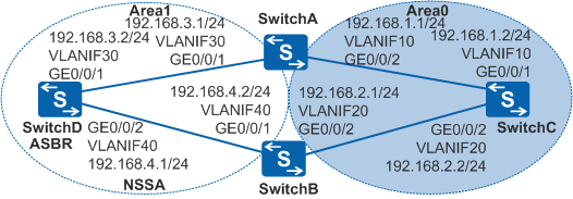
As shown in Figure 1, OSPF is running on four switches, and the entire OSPF network is partitioned into Area0 and Area1. It is required that devices in Area1 do not receive external routes imported by other OSPF areas but they import external routes through the ASBR to communicate with external networks. Because there are a large number of services configured on SwitchB, SwitchA needs to be specified as a translator to translate Type7 LSAs to Type5 LSAs and send them to other OSPF areas.

In this scenario, ensure that all connected interfaces have STP disabled. If STP is enabled and VLANIF interfaces of switches are used to construct a Layer 3 ring network, an interface on the network will be blocked. As a result, Layer 3 services on the network cannot run normally.
Configuration Roadmap
The configuration roadmap is as follows:
Configure basic OSPF functions on each switch to implement basic connections on the OSPF network.
Configure Area1 as an NSSA, configure static routes on SwitchD, and import the static routes to the OSPF routing table. In this way, switches in Area1 can communicate with external networks only through SwitchD.
Configure SwitchA as a translator so that it can translate Type7 LSAs to Type5 LSAs and then send them to other OSPF areas.
Procedure
- Configure VLANs for interfaces.
# Configure SwitchA. The configurations of SwitchB, SwitchC, and SwitchD are similar to the configuration of SwitchA.
<HUAWEI> system-view
[HUAWEI] sysname SwitchA
[SwitchA] vlan batch 10 30
[SwitchA] interface gigabitethernet 0/0/1
[SwitchA-GigabitEthernet0/0/1] port link-type trunk
[SwitchA-GigabitEthernet0/0/1] port trunk allow-pass vlan 30
[SwitchA-GigabitEthernet0/0/1] quit
[SwitchA] interface gigabitethernet 0/0/2
[SwitchA-GigabitEthernet0/0/2] port link-type trunk
[SwitchA-GigabitEthernet0/0/2] port trunk allow-pass vlan 10
[SwitchA-GigabitEthernet0/0/2] quit
- Configure an IP address for each VLANIF interface.
# Configure SwitchA. The configurations of SwitchB, SwitchC, and SwitchD are similar to the configuration of SwitchA.
[SwitchA] interface vlanif 10
[SwitchA-Vlanif10] ip address 192.168.1.1 24
[SwitchA-Vlanif10] quit
[SwitchA] interface vlanif 30
[SwitchA-Vlanif30] ip address 192.168.3.1 24
[SwitchA-Vlanif30] quit
- Configure basic OSPF functions.
# Configure SwitchA.
[SwitchA] ospf 1 router-id 10.1.1.1
[SwitchA-ospf-1] area 0
[SwitchA-ospf-1-area-0.0.0.0] network 192.168.1.0 0.0.0.255
[SwitchA-ospf-1-area-0.0.0.0] quit
[SwitchA-ospf-1] area 1
[SwitchA-ospf-1-area-0.0.0.1] network 192.168.3.0 0.0.0.255
[SwitchA-ospf-1-area-0.0.0.1] quit
[SwitchA-ospf-1] quit
# Configure SwitchB.
[SwitchB] ospf 1 router-id 10.2.2.2
[SwitchB-ospf-1] area 0
[SwitchB-ospf-1-area-0.0.0.0] network 192.168.2.0 0.0.0.255
[SwitchB-ospf-1-area-0.0.0.0] quit
[SwitchB-ospf-1] area 1
[SwitchB-ospf-1-area-0.0.0.1] network 192.168.4.0 0.0.0.255
[SwitchB-ospf-1-area-0.0.0.1] quit
[SwitchB-ospf-1] quit
# Configure SwitchC.
[SwitchC] ospf 1 router-id 10.3.3.3
[SwitchC-ospf-1] area 0
[SwitchC-ospf-1-area-0.0.0.0] network 192.168.1.0 0.0.0.255
[SwitchC-ospf-1-area-0.0.0.0] network 192.168.2.0 0.0.0.255
[SwitchC-ospf-1-area-0.0.0.0] quit
[SwitchC-ospf-1] quit
# Configure SwitchD.
[SwitchD] ospf 1 router-id 10.4.4.4
[SwitchD-ospf-1] area 1
[SwitchD-ospf-1-area-0.0.0.1] network 192.168.3.0 0.0.0.255
[SwitchD-ospf-1-area-0.0.0.1] network 192.168.4.0 0.0.0.255
[SwitchD-ospf-1-area-0.0.0.1] quit
[SwitchD-ospf-1] quit
- Configure Area1 as an NSSA.
# Configure SwitchA.
[SwitchA] ospf 1
[SwitchA-ospf-1] area 1
[SwitchA-ospf-1-area-0.0.0.1] nssa
[SwitchA-ospf-1-area-0.0.0.1] quit
[SwitchA-ospf-1] quit
# Configure SwitchB.
[SwitchB] ospf 1
[SwitchB-ospf-1] area 1
[SwitchB-ospf-1-area-0.0.0.1] nssa
[SwitchB-ospf-1-area-0.0.0.1] quit
[SwitchB-ospf-1] quit
# Configure SwitchD.
[SwitchD] ospf 1
[SwitchD-ospf-1] area 1
[SwitchD-ospf-1-area-0.0.0.1] nssa
[SwitchD-ospf-1-area-0.0.0.1] quit
[SwitchD-ospf-1] quit
- Configure SwitchD to import static routes.
[SwitchD] ip route-static 172.16.0.0 16 null 0
[SwitchD] ospf 1
[SwitchD-ospf-1] import-route static
[SwitchD-ospf-1] quit
# Check the OSPF routing table on SwitchC.
[SwitchC] display ospf routing

          OSPF Process 1 with Router ID 10.3.3.3
                   Routing Tables

 Routing for Network
 Destination        Cost  Type       NextHop         AdvRouter       Area
 192.168.1.0/24     1     Transit    192.168.1.2     10.3.3.3       0.0.0.0
 192.168.2.0/24     1     Transit    192.168.2.2     10.3.3.3       0.0.0.0
 192.168.3.0/24     2     Inter-area 192.168.1.1     10.1.1.1       0.0.0.0
 192.168.4.0/24     2     Inter-area 192.168.2.1     10.2.2.2       0.0.0.0

 Routing for ASEs
 Destination        Cost      Type       Tag    NextHop         AdvRouter
 172.16.0.0/16       1         Type2       1     192.168.1.1     10.2.2.2

 Total Nets: 5
 Intra Area: 2  Inter Area: 2  ASE: 1  NSSA: 0
The preceding command output shows that AS external routes imported by the NSSA are advertised to other areas through SwitchB. That is, SwitchB translates Type7 LSAs to Type5 LSAs. This is because that OSPF selects the ABR (SwitchB) with a greater router ID as the translator.
- Configure SwitchA as a translator.
[SwitchA] ospf 1
[SwitchA-ospf-1] area 1
[SwitchA-ospf-1-area-0.0.0.1] nssa translator-always
[SwitchA-ospf-1-area-0.0.0.1] quit
[SwitchA-ospf-1] quit
- Verify the configuration.
# Check the OSPF routing table on SwitchC after 40 seconds.
[SwitchC] display ospf routing

          OSPF Process 1 with Router ID 10.3.3.3
                   Routing Tables

 Routing for Network
 Destination        Cost  Type       NextHop         AdvRouter       Area
 192.168.1.0/24     1     Transit    192.168.1.2     10.3.3.3       0.0.0.0
 192.168.2.0/24     1     Transit    192.168.2.2     10.3.3.3       0.0.0.0
 192.168.3.0/24     2     Inter-area 192.168.1.1     10.1.1.1       0.0.0.0
 192.168.4.0/24     2     Inter-area 192.168.2.1     10.2.2.2       0.0.0.0

 Routing for ASEs
 Destination        Cost      Type       Tag    NextHop         AdvRouter
 172.16.0.0/16       1         Type2       1     192.168.1.1     10.1.1.1

 Total Nets: 5
 Intra Area: 2  Inter Area: 2  ASE: 1  NSSA: 0
The preceding command output shows that AS external routes imported by the NSSA are advertised to other areas through SwitchA. That is, SwitchA functions as the translator.
By default, both the new and original translators function for 40 seconds. After 40 seconds, translation is performed by only the new translator.
Configuration Files
SwitchA configuration file
#
sysname SwitchA
#
vlan batch 10 30
#
interface Vlanif10
 ip address 192.168.1.1 255.255.255.0
#
interface Vlanif30
 ip address 192.168.3.1 255.255.255.0
#
interface GigabitEthernet0/0/1
 port link-type trunk
 port trunk allow-pass vlan 30
#
interface GigabitEthernet0/0/2
 port link-type trunk
 port trunk allow-pass vlan 10
#
ospf 1 router-id 10.1.1.1
 area 0.0.0.0
  network 192.168.1.0 0.0.0.255
 area 0.0.0.1
  network 192.168.3.0 0.0.0.255
  nssa translator-always
#
return
SwitchB configuration file
#
sysname SwitchB
#
vlan batch 20 40
#
interface Vlanif20
 ip address 192.168.2.1 255.255.255.0
#
interface Vlanif40
 ip address 192.168.4.2 255.255.255.0
#
interface GigabitEthernet0/0/1
 port link-type trunk
 port trunk allow-pass vlan 40
#
interface GigabitEthernet0/0/2
 port link-type trunk
 port trunk allow-pass vlan 20
#
ospf 1 router-id 10.2.2.2
 area 0.0.0.0
  network 192.168.2.0 0.0.0.255
 area 0.0.0.1
  network 192.168.4.0 0.0.0.255
  nssa
#
return
SwitchC configuration file
#
sysname SwitchC
#
vlan batch 10 20
#
interface Vlanif10
 ip address 192.168.1.2 255.255.255.0
#
interface Vlanif20
 ip address 192.168.2.2 255.255.255.0
#
interface GigabitEthernet0/0/1
 port link-type trunk
 port trunk allow-pass vlan 10
#
interface GigabitEthernet0/0/2
 port link-type trunk
 port trunk allow-pass vlan 20
#
ospf 1 router-id 10.3.3.3
 area 0.0.0.0
  network 192.168.1.0 0.0.0.255
  network 192.168.2.0 0.0.0.255
#
return
SwitchD configuration file
#
sysname SwitchD
#
vlan batch 30 40
#
interface Vlanif30
 ip address 192.168.3.2 255.255.255.0
#
interface Vlanif40
 ip address 192.168.4.1 255.255.255.0
#
interface GigabitEthernet0/0/1
 port link-type trunk
 port trunk allow-pass vlan 30
#
interface GigabitEthernet0/0/2
 port link-type trunk
 port trunk allow-pass vlan 40
#
ospf 1 router-id 10.4.4.4
 import-route static
 area 0.0.0.1
  network 192.168.3.0 0.0.0.255
  network 192.168.4.0 0.0.0.255
  nssa
#
ip route-static 172.16.0.0 255.255.0.0 NULL0
#
return