Example for Configuring OSPF Load Balancing
Networking Requirements
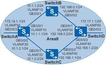
On an OSPF network, as shown in Figure 1, four switches all belong to Area0. Load balancing needs to be configured so that the traffic from SwitchA can be sent to SwitchD through SwitchB and SwitchC.

In this scenario, ensure that all connected interfaces have STP disabled. If STP is enabled and VLANIF interfaces of switches are used to construct a Layer 3 ring network, an interface on the network will be blocked. As a result, Layer 3 services on the network cannot run normally.
Configuration Roadmap
The configuration roadmap is as follows:
Configure basic OSPF functions on each switch to implement basic connections on the OSPF network.
- Configure load balancing on SwitchA.
Procedure
- Configure VLANs for interfaces.
# Configure SwitchA. The configurations of SwitchB, SwitchC, and SwitchD are similar to the configuration of SwitchA.
<HUAWEI> system-view
[HUAWEI] sysname SwitchA
[SwitchA] vlan batch 10 20 50
[SwitchA] interface gigabitethernet 0/0/1
[SwitchA-GigabitEthernet0/0/1] port link-type trunk
[SwitchA-GigabitEthernet0/0/1] port trunk allow-pass vlan 10
[SwitchA-GigabitEthernet0/0/1] quit
[SwitchA] interface gigabitethernet 0/0/2
[SwitchA-GigabitEthernet0/0/2] port link-type trunk
[SwitchA-GigabitEthernet0/0/2] port trunk allow-pass vlan 20
[SwitchA-GigabitEthernet0/0/2] quit
[SwitchA] interface gigabitethernet 0/0/3
[SwitchA-GigabitEthernet0/0/3] port link-type trunk
[SwitchA-GigabitEthernet0/0/3] port trunk allow-pass vlan 50
[SwitchA-GigabitEthernet0/0/3] quit
- Configure an IP address for each VLANIF interface.
# Configure SwitchA. The configurations of SwitchB, SwitchC, and SwitchD are similar to the configuration of SwitchA.
[SwitchA] interface vlanif 10
[SwitchA-Vlanif10] ip address 10.1.1.1 24
[SwitchA-Vlanif10] quit
[SwitchA] interface vlanif 20
[SwitchA-Vlanif20] ip address 10.1.2.1 24
[SwitchA-Vlanif20] quit
[SwitchA] interface vlanif 50
[SwitchA-Vlanif50] ip address 172.16.1.1 24
[SwitchA-Vlanif50] quit
- Configure basic OSPF functions.
# Configure SwitchA.
[SwitchA] ospf 1 router-id 10.10.10.1
[SwitchA-ospf-1] area 0
[SwitchA-ospf-1-area-0.0.0.0] network 172.16.1.0 0.0.0.255
[SwitchA-ospf-1-area-0.0.0.0] network 10.1.1.0 0.0.0.255
[SwitchA-ospf-1-area-0.0.0.0] network 10.1.2.0 0.0.0.255
[SwitchA-ospf-1-area-0.0.0.0] quit
[SwitchA-ospf-1] quit
# Configure SwitchB.
[SwitchB] ospf 1 router-id 10.10.10.2
[SwitchB-ospf-1] area 0
[SwitchB-ospf-1-area-0.0.0.0] network 10.1.1.0 0.0.0.255
[SwitchB-ospf-1-area-0.0.0.0] network 192.168.0.0 0.0.0.255
[SwitchB-ospf-1-area-0.0.0.0] quit
[SwitchB-ospf-1] quit
# Configure SwitchC.
[SwitchC] ospf 1 router-id 10.10.10.3
[SwitchC-ospf-1] area 0
[SwitchC-ospf-1-area-0.0.0.0] network 10.1.2.0 0.0.0.255
[SwitchC-ospf-1-area-0.0.0.0] network 192.168.1.0 0.0.0.255
[SwitchC-ospf-1-area-0.0.0.0] quit
[SwitchC-ospf-1] quit
# Configure SwitchD.
[SwitchD] ospf 1 router-id 10.10.10.4
[SwitchD-ospf-1] area 0
[SwitchD-ospf-1-area-0.0.0.0] network 192.168.0.0 0.0.0.255
[SwitchD-ospf-1-area-0.0.0.0] network 192.168.1.0 0.0.0.255
[SwitchD-ospf-1-area-0.0.0.0] network 172.17.1.0 0.0.0.255
[SwitchD-ospf-1-area-0.0.0.0] quit
[SwitchD-ospf-1] quit
# Check the routing table on SwitchA.
[SwitchA] display ip routing-table
Route Flags: R - relay, D - download to fib, T - to vpn-instance
------------------------------------------------------------------------------
Routing Tables: Public
         Destinations : 11       Routes : 12

Destination/Mask    Proto   Pre  Cost      Flags NextHop         Interface

       10.1.1.0/24  Direct  0    0           D   10.1.1.1        Vlanif10
       10.1.1.1/32  Direct  0    0           D   127.0.0.1       Vlanif10
       10.1.2.0/24  Direct  0    0           D   10.1.2.1        Vlanif20
       10.1.2.1/32  Direct  0    0           D   127.0.0.1       Vlanif20
      127.0.0.0/8   Direct  0    0           D   127.0.0.1       InLoopBack0
      127.0.0.1/32  Direct  0    0           D   127.0.0.1       InLoopBack0
     172.16.1.0/24  Direct  0    0           D   172.16.1.1      Vlanif50
     172.16.1.1/32  Direct  0    0           D   127.0.0.1       Vlanif50
     172.17.1.0/24  OSPF    10   3           D   10.1.1.2        Vlanif10
                    OSPF    10   3           D   10.1.2.2        Vlanif20
    192.168.0.0/24  OSPF    10   2           D   10.1.1.2        Vlanif10
    192.168.1.0/24  OSPF    10   2           D   10.1.2.2        Vlanif20
The preceding command output shows that both next hops of SwitchA, namely, 10.1.1.2 (SwitchB) and 10.1.2.2 (SwitchC), become valid. This is because that the default quantity of equal-cost routes allowed for a switch is 8.
- Configure a weight for an equal-cost route on SwitchA.
If you do not want load balancing between SwitchB and SwitchC, set a weight for one of the equal-cost routes to specify the next hop.
[SwitchA] ospf 1
[SwitchA-ospf-1] nexthop 10.1.2.2 weight 1
[SwitchA-ospf-1] quit
# Check the routing table on SwitchA.
[SwitchA] display ip routing-table
Route Flags: R - relay, D - download to fib, T - to vpn-instance
------------------------------------------------------------------------------
Routing Tables: Public
         Destinations : 11       Routes : 11

Destination/Mask    Proto   Pre  Cost      Flags NextHop         Interface

       10.1.1.0/24  Direct  0    0           D   10.1.1.1        Vlanif10
       10.1.1.1/32  Direct  0    0           D   127.0.0.1       Vlanif10
       10.1.2.0/24  Direct  0    0           D   10.1.2.1        Vlanif20
       10.1.2.1/32  Direct  0    0           D   127.0.0.1       Vlanif20
      127.0.0.0/8   Direct  0    0           D   127.0.0.1       InLoopBack0
      127.0.0.1/32  Direct  0    0           D   127.0.0.1       InLoopBack0
     172.16.1.0/24  Direct  0    0           D   172.16.1.1      Vlanif50
     172.16.1.1/32  Direct  0    0           D   127.0.0.1       Vlanif50
     172.17.1.0/24  OSPF    10   3           D   10.1.2.2        Vlanif20
    192.168.0.0/24  OSPF    10   2           D   10.1.1.2        Vlanif10
    192.168.1.0/24  OSPF    10   2           D   10.1.2.2        Vlanif20
The preceding command output shows that the priority of the next hop 10.1.2.2 (SwitchC) with weight 1 is higher than that of 10.1.1.2 (SwitchB). Therefore, OSPF selects the route with the next hop 10.1.2.2 as the optimal route.
Configuration Files
SwitchA configuration file
#
sysname SwitchA
#
vlan batch 10 20 50
#
interface Vlanif10
 ip address 10.1.1.1 255.255.255.0
#
interface Vlanif20
 ip address 10.1.2.1 255.255.255.0
#
interface Vlanif50
 ip address 172.16.1.1 255.255.255.0
#
interface GigabitEthernet0/0/1
 port link-type trunk
 port trunk allow-pass vlan 10
#
interface GigabitEthernet0/0/2
 port link-type trunk
 port trunk allow-pass vlan 20
#
interface GigabitEthernet0/0/3
 port link-type trunk
 port trunk allow-pass vlan 50
#
ospf 1 router-id 10.10.10.1
 nexthop 10.1.2.2 weight 1
 area 0.0.0.0
  network 10.1.1.0 0.0.0.255
  network 10.1.2.0 0.0.0.255
  network 172.16.1.0 0.0.0.255
#
return
SwitchB configuration file
#
sysname SwitchB
#
vlan batch 10 30
#
interface Vlanif10
 ip address 10.1.1.2 255.255.255.0
#
interface Vlanif30
 ip address 192.168.0.1 255.255.255.0
#
interface GigabitEthernet0/0/1
 port link-type trunk
 port trunk allow-pass vlan 10
#
interface GigabitEthernet0/0/2
 port link-type trunk
 port trunk allow-pass vlan 30
#
ospf 1 router-id 10.10.10.2
 area 0.0.0.0
  network 10.1.1.0 0.0.0.255
  network 192.168.0.0 0.0.0.255
#
return
SwitchC configuration file
#
sysname SwitchC
#
vlan batch 20 40
#
interface Vlanif20
 ip address 10.1.2.2 255.255.255.0
#
interface Vlanif40
 ip address 192.168.1.1 255.255.255.0
#
interface GigabitEthernet0/0/1
 port link-type trunk
 port trunk allow-pass vlan 20
#
interface GigabitEthernet0/0/2
 port link-type trunk
 port trunk allow-pass vlan 40
#
ospf 1 router-id 10.10.10.3
 area 0.0.0.0
  network 10.1.2.0 0.0.0.255
  network 192.168.1.0 0.0.0.255
#
return
SwitchD configuration file
#
sysname SwitchD
#
vlan batch 30 40 60
#
interface Vlanif30
 ip address 192.168.0.2 255.255.255.0
#
interface Vlanif40
 ip address 192.168.1.2 255.255.255.0
#
interface Vlanif60
 ip address 172.17.1.1 255.255.255.0
#
interface GigabitEthernet0/0/1
 port link-type trunk
 port trunk allow-pass vlan 30
#
interface GigabitEthernet0/0/2
 port link-type trunk
 port trunk allow-pass vlan 40
#
interface GigabitEthernet0/0/3
 port link-type trunk
 port trunk allow-pass vlan 60
#
ospf 1 router-id 10.10.10.4
 area 0.0.0.0
  network 172.17.1.0 0.0.0.255
  network 192.168.0.0 0.0.0.255
  network 192.168.1.0 0.0.0.255
#
return