Example for Configuring OSPF-BGP Synchronization
Networking Requirements
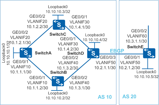
As shown in Figure 1, an EBGP connection is established between SwitchD and SwitchE. IBGP connections are established between switches in AS 10, and OSPF is used as an IGP protocol. OSPF-BGP synchronization needs to be enabled on SwitchB so that the traffic from SwitchA to AS 20 will not be interrupted when SwitchB restarts.

In this scenario, ensure that all connected interfaces have STP disabled. If STP is enabled and VLANIF interfaces of switches are used to construct a Layer 3 ring network, an interface on the network will be blocked. As a result, Layer 3 services on the network cannot run normally.
Configuration Roadmap
The configuration roadmap is as follows:
Configure VLANs for interfaces, VLANIF interfaces for the VLANs, and IP addresses for each VLANIF interface to implement communication within network segments.
Configure basic OSPF functions and IBGP connections on SwitchA, SwitchB, SwitchC, and SwitchD (excluding 10.2.1.1/30) to implement device connections within AS 10.
Configure EBGP connections between SwitchD and SwitchE, and import direct routes and OSPF routes to implement communication between AS 10 and AS 20.
Set the OSPF protocol cost to 2 on SwitchC so that SwitchA selects only SwitchB as the intermediate router to the network segment 10.2.1.0 and SwitchC becomes the backup of SwitchB.
Enable OSPF-BGP synchronization on SwitchB so that the traffic from SwitchA to AS 20 will not be interrupted when SwitchB restarts.
Procedure
- Configure VLANs for interfaces.
# Configure SwitchA. The configurations of SwitchB, SwitchC, SwitchD, and SwitchE are similar to the configuration of SwitchA.
<HUAWEI> system-view
[HUAWEI] sysname SwitchA
[SwitchA] vlan batch 10 20
[SwitchA] interface gigabitethernet 0/0/1
[SwitchA-GigabitEthernet0/0/1] port link-type trunk
[SwitchA-GigabitEthernet0/0/1] port trunk allow-pass vlan 10
[SwitchA-GigabitEthernet0/0/1] quit
[SwitchA] interface gigabitethernet 0/0/2
[SwitchA-GigabitEthernet0/0/2] port link-type trunk
[SwitchA-GigabitEthernet0/0/2] port trunk allow-pass vlan 20
[SwitchA-GigabitEthernet0/0/2] quit
- Assign IP addresses to the VLANIF interfaces and loopback interfaces.
# Configure SwitchA. The configurations of SwitchB, SwitchC, SwitchD, and SwitchE are similar to the configuration of SwitchA.
[SwitchA] interface vlanif 10
[SwitchA-Vlanif10] ip address 10.1.1.1 30
[SwitchA-Vlanif10] quit
[SwitchA] interface vlanif 20
[SwitchA-Vlanif20] ip address 10.1.2.1 30
[SwitchA-Vlanif20] quit
[SwitchA] interface loopback 0
[SwitchA-LoopBack0] ip address 10.10.10.1 32
[SwitchA-LoopBack0] quit
- Configure basic OSPF functions.
# Configure SwitchA. The configurations of SwitchB, SwitchC, and SwitchD are similar to the configuration of SwitchA.
[SwitchA] router id 10.10.10.1
[SwitchA] ospf 1
[SwitchA-ospf-1] area 0
[SwitchA-ospf-1-area-0.0.0.0] network 10.10.10.1 0.0.0.0
[SwitchA-ospf-1-area-0.0.0.0] network 10.1.1.0 0.0.0.3
[SwitchA-ospf-1-area-0.0.0.0] network 10.1.2.0 0.0.0.3
[SwitchA-ospf-1-area-0.0.0.0] quit
[SwitchA-ospf-1] quit
- Configure IBGP fully meshed connections.
# Configure SwitchA.
[SwitchA] bgp 10
[SwitchA-bgp] peer 10.10.10.2 as-number 10
[SwitchA-bgp] peer 10.10.10.2 connect-interface LoopBack 0
[SwitchA-bgp] peer 10.10.10.3 as-number 10
[SwitchA-bgp] peer 10.10.10.3 connect-interface LoopBack 0
[SwitchA-bgp] peer 10.10.10.4 as-number 10
[SwitchA-bgp] peer 10.10.10.4 connect-interface LoopBack 0
[SwitchA-bgp] quit
# Configure SwitchB.
[SwitchB] bgp 10
[SwitchB-bgp] peer 10.10.10.1 as-number 10
[SwitchB-bgp] peer 10.10.10.1 connect-interface LoopBack 0
[SwitchB-bgp] peer 10.10.10.3 as-number 10
[SwitchB-bgp] peer 10.10.10.3 connect-interface LoopBack 0
[SwitchB-bgp] peer 10.10.10.4 as-number 10
[SwitchB-bgp] peer 10.10.10.4 connect-interface LoopBack 0
[SwitchB-bgp] quit
# Configure SwitchC.
[SwitchC] bgp 10
[SwitchC-bgp] peer 10.10.10.1 as-number 10
[SwitchC-bgp] peer 10.10.10.1 connect-interface LoopBack 0
[SwitchC-bgp] peer 10.10.10.2 as-number 10
[SwitchC-bgp] peer 10.10.10.2 connect-interface LoopBack 0
[SwitchC-bgp] peer 10.10.10.4 as-number 10
[SwitchC-bgp] peer 10.10.10.4 connect-interface LoopBack 0
[SwitchC-bgp] quit
# Configure SwitchD.
[SwitchD] bgp 10
[SwitchD-bgp] peer 10.10.10.1 as-number 10
[SwitchD-bgp] peer 10.10.10.1 connect-interface LoopBack 0
[SwitchD-bgp] peer 10.10.10.2 as-number 10
[SwitchD-bgp] peer 10.10.10.2 connect-interface LoopBack 0
[SwitchD-bgp] peer 10.10.10.3 as-number 10
[SwitchD-bgp] peer 10.10.10.3 connect-interface LoopBack 0
[SwitchD-bgp] quit
- Establish an EBGP connection.
# Configure SwitchD.
[SwitchD] bgp 10
[SwitchD-bgp] peer 10.2.1.2 as-number 20
[SwitchD-bgp] import-route direct
[SwitchD-bgp] import-route ospf 1
[SwitchD-bgp] quit
# Configure SwitchE.
[SwitchE] bgp 20
[SwitchE-bgp] router-id 10.10.10.5
[SwitchE-bgp] peer 10.2.1.1 as-number 10
[SwitchE-bgp] ipv4-family unicast
[SwitchE-bgp-af-ipv4] network 10.3.1.0 30
[SwitchE-bgp-af-ipv4] quit
[SwitchE-bgp] quit
- Configure a cost for OSPF on SwitchC.
[SwitchC] interface vlanif 20
[SwitchC-Vlanif20] ospf cost 2
[SwitchC-Vlanif20] quit
[SwitchC] interface vlanif 30
[SwitchC-Vlanif30] ospf cost 2
[SwitchC-Vlanif30] quit
# Check the routing table on SwitchA. The routing table shows that the route to the destination network segment 10.3.1.0 is learned through BGP and the outbound interface is Vlanif10.
[SwitchA] display ip routing-table
Route Flags: R - relay, D - download to fib, T - to vpn-instance
------------------------------------------------------------------------------
Routing Tables: Public
         Destinations : 14       Routes : 15

Destination/Mask    Proto   Pre  Cost      Flags NextHop         Interface

       10.1.1.0/30  Direct  0    0           D   10.1.1.1        Vlanif10
       10.1.1.1/32  Direct  0    0           D   127.0.0.1       Vlanif10
       10.1.2.0/30  Direct  0    0           D   10.1.2.1        Vlanif20
       10.1.2.1/32  Direct  0    0           D   127.0.0.1       Vlanif20
       10.1.3.0/30  OSPF    10   2           D   10.1.1.2        Vlanif10
       10.1.4.0/30  OSPF    10   3           D   10.1.2.2        Vlanif20
                    OSPF    10   3           D   10.1.1.2        Vlanif10
       10.2.1.0/30  IBGP    255  0          RD   10.10.10.4      Vlanif10
       10.3.1.0/30  IBGP    255  0          RD   10.2.1.2        Vlanif10
     10.10.10.1/32  Direct  0    0           D   127.0.0.1       LoopBack0
     10.10.10.2/32  OSPF    10   1           D   10.1.1.2        Vlanif10
     10.10.10.3/32  OSPF    10   1           D   10.1.2.2        Vlanif20
     10.10.10.4/32  OSPF    10   2           D   10.1.1.2        Vlanif10
      127.0.0.0/8   Direct  0    0           D   127.0.0.1       InLoopBack0
      127.0.0.1/32  Direct  0    0           D   127.0.0.1       InLoopBack0
# Check the routing table on SwitchB.
[SwitchB] display ip routing-table
Route Flags: R - relay, D - download to fib, T - to vpn-instance
------------------------------------------------------------------------------
Routing Tables: Public
         Destinations : 14       Routes : 15

Destination/Mask    Proto   Pre  Cost      Flags NextHop         Interface

       10.1.1.0/30  Direct  0    0           D   10.1.1.2        Vlanif10
       10.1.1.2/32  Direct  0    0           D   127.0.0.1       Vlanif10
       10.1.2.0/30  OSPF    10   2           D   10.1.1.1        Vlanif10
       10.1.3.0/30  Direct  0    0           D   10.1.3.1        Vlanif40
       10.1.3.1/32  Direct  0    0           D   127.0.0.1       Vlanif40
       10.1.4.0/30  OSPF    10   2           D   10.1.3.2        Vlanif40
       10.2.1.0/30  IBGP    255  0          RD   10.10.10.4      Vlanif40
       10.3.1.0/30  IBGP    255  0          RD   10.2.1.2        Vlanif40
     10.10.10.1/32  OSPF    10   1           D   10.1.1.1        Vlanif10
     10.10.10.2/32  Direct  0    0           D   127.0.0.1       LoopBack0
     10.10.10.3/32  OSPF    10   2           D   10.1.1.1        Vlanif10
                    OSPF    10   2           D   10.1.3.2        Vlanif40
     10.10.10.4/32  OSPF    10   1           D   10.1.3.2        Vlanif40
      127.0.0.0/8   Direct  0    0           D   127.0.0.1       InLoopBack0
      127.0.0.1/32  Direct  0    0           D   127.0.0.1       InLoopBack0
The preceding command output shows that the route to the destination network segment 10.3.1.0 is learned by SwitchB through BGP and the outbound interface is Vlanif40. The routes to the network segments 10.1.2.0 and 10.1.4.0 are learned through OSPF, and the costs of the routes are both 2.
- Configure OSPF-BGP synchronization on SwitchB.
[SwitchB] ospf
[SwitchB-ospf-1] stub-router on-startup
[SwitchB-ospf-1] return
- Verify the configuration.
# Save the configurations.
<SwitchB> saveThe system displays a message asking whether you want to save the configurations. Enter y.
# Restart SwitchB.
<SwitchB> rebootThe system displays a message asking whether you want to continue with a system reboot. Enter y.
# Check the routing table on SwitchA. The routing table shows that the route to the destination network segment 10.3.1.0 is learned through BGP and the outbound interface is Vlanif20.
[SwitchA] display ip routing-table
Route Flags: R - relay, D - download to fib, T - to vpn-instance
------------------------------------------------------------------------------
Routing Tables: Public
         Destinations : 10       Routes : 10

Destination/Mask    Proto   Pre  Cost      Flags NextHop         Interface

       10.1.2.0/30  Direct  0    0           D   10.1.2.1        Vlanif20
       10.1.2.1/32  Direct  0    0           D   127.0.0.1       Vlanif20
       10.1.4.0/30  OSPF    10   3           D   10.1.2.2        Vlanif20
       10.2.1.0/30  IBGP    255  0          RD   10.10.10.4      Vlanif20
       10.3.1.0/30  IBGP    255  0          RD   10.2.1.2        Vlanif20
     10.10.10.1/32  Direct  0    0           D   127.0.0.1       LoopBack0
     10.10.10.3/32  OSPF    10   1           D   10.1.2.2        Vlanif20
     10.10.10.4/32  OSPF    10   3           D   10.1.2.2        Vlanif20
      127.0.0.0/8   Direct  0    0           D   127.0.0.1       InLoopBack0
      127.0.0.1/32  Direct  0    0           D   127.0.0.1       InLoopBack0
# Check the routing table on SwitchB. The routing table shows that only OSPF routes exist in the routing table and their costs are at least 65535. This is because that OSPF (IGP) routes converge faster than BGP routes.
<SwitchB> display ip routing-table
Route Flags: R - relay, D - download to fib, T - to vpn-instance
------------------------------------------------------------------------------
Routing Tables: Public
         Destinations : 12       Routes : 13

Destination/Mask    Proto   Pre  Cost      Flags NextHop         Interface

       10.1.1.0/30  Direct  0    0           D   10.1.1.2        Vlanif10
       10.1.1.2/32  Direct  0    0           D   127.0.0.1       Vlanif10
       10.1.2.0/30  OSPF    10   65536       D   10.1.1.1        Vlanif10
       10.1.3.0/30  Direct  0    0           D   10.1.3.1        Vlanif40
       10.1.3.1/32  Direct  0    0           D   127.0.0.1       Vlanif40
       10.1.4.0/30  OSPF    10   65536       D   10.1.3.2        Vlanif40
     10.10.10.1/32  OSPF    10   65535       D   10.1.1.1        Vlanif10
     10.10.10.2/32  Direct  0    0           D   127.0.0.1       LoopBack0
     10.10.10.3/32  OSPF    10   65536       D   10.1.1.1        Vlanif10
                    OSPF    10   65536       D   10.1.3.2        Vlanif40
     10.10.10.4/32  OSPF    10   65535       D   10.1.3.2        Vlanif40
      127.0.0.0/8   Direct  0    0           D   127.0.0.1       InLoopBack0
      127.0.0.1/32  Direct  0    0           D   127.0.0.1       InLoopBack0
# After the network is stable, check the routing table of SwitchB again.
<SwitchB> display ip routing-table
Route Flags: R - relay, D - download to fib, T - to vpn-instance
------------------------------------------------------------------------------
Routing Tables: Public
         Destinations : 14       Routes : 15

Destination/Mask    Proto   Pre  Cost      Flags NextHop         Interface

       10.1.1.0/30  Direct  0    0           D   10.1.1.2        Vlanif10
       10.1.1.2/32  Direct  0    0           D   127.0.0.1       Vlanif10
       10.1.2.0/30  OSPF    10   2           D   10.1.1.1        Vlanif10
       10.1.3.0/30  Direct  0    0           D   10.1.3.1        Vlanif40
       10.1.3.1/32  Direct  0    0           D   127.0.0.1       Vlanif40
       10.1.4.0/30  OSPF    10   2           D   10.1.3.2        Vlanif40
       10.2.1.0/30  IBGP    255  0          RD   10.10.10.4      Vlanif40
       10.3.1.0/30  IBGP    255  0          RD   10.2.1.2        Vlanif40
     10.10.10.1/32  OSPF    10   1           D   10.1.1.1        Vlanif10
     10.10.10.2/32  Direct  0    0           D   127.0.0.1       LoopBack0
     10.10.10.3/32  OSPF    10   2           D   10.1.1.1        Vlanif10
                    OSPF    10   2           D   10.1.3.2        Vlanif40
     10.10.10.4/32  OSPF    10   1           D   10.1.3.2        Vlanif40
      127.0.0.0/8   Direct  0    0           D   127.0.0.1       InLoopBack0
      127.0.0.1/32  Direct  0    0           D   127.0.0.1       InLoopBack0
The preceding command output shows that, after BGP routes on SwitchB converge, the routing information restores.
Configuration Files
SwitchA configuration file
#
sysname SwitchA
#
router id 10.10.10.1
#
vlan batch 10 20
#
interface Vlanif10
 ip address 10.1.1.1 255.255.255.252
#
interface Vlanif20
 ip address 10.1.2.1 255.255.255.252
#
interface GigabitEthernet0/0/1
 port link-type trunk
 port trunk allow-pass vlan 10
#
interface GigabitEthernet0/0/2
 port link-type trunk
 port trunk allow-pass vlan 20
#
interface LoopBack0
 ip address 10.10.10.1 255.255.255.255
#
bgp 10
 peer 10.10.10.2 as-number 10
 peer 10.10.10.2 connect-interface LoopBack0
 peer 10.10.10.3 as-number 10
 peer 10.10.10.3 connect-interface LoopBack0
 peer 10.10.10.4 as-number 10
 peer 10.10.10.4 connect-interface LoopBack0
 #
 ipv4-family unicast
  undo synchronization
  peer 10.10.10.2 enable
  peer 10.10.10.3 enable
  peer 10.10.10.4 enable
#
ospf 1
 area 0.0.0.0
  network 10.1.1.0 0.0.0.3
  network 10.1.2.0 0.0.0.3
  network 10.10.10.1 0.0.0.0
#
return
SwitchB configuration file
#
sysname SwitchB
#
router id 10.10.10.2
#
vlan batch 10 40
#
interface Vlanif10
 ip address 10.1.1.2 255.255.255.252
#
interface Vlanif40
 ip address 10.1.3.1 255.255.255.252
#
interface GigabitEthernet0/0/1
 port link-type trunk
 port trunk allow-pass vlan 10
#
interface GigabitEthernet0/0/2
 port link-type trunk
 port trunk allow-pass vlan 40
#
interface LoopBack0
 ip address 10.10.10.2 255.255.255.255
#
bgp 10
 peer 10.10.10.1 as-number 10
 peer 10.10.10.1 connect-interface LoopBack0
 peer 10.10.10.3 as-number 10
 peer 10.10.10.3 connect-interface LoopBack0
 peer 10.10.10.4 as-number 10
 peer 10.10.10.4 connect-interface LoopBack0
 #
 ipv4-family unicast
  undo synchronization
  peer 10.10.10.1 enable
  peer 10.10.10.3 enable
  peer 10.10.10.4 enable
#
ospf 1
 stub-router on-startup
 area 0.0.0.0
  network 10.1.1.0 0.0.0.3
  network 10.1.3.0 0.0.0.3
  network 10.10.10.2 0.0.0.0
#
return
SwitchC configuration file
#
sysname SwitchC
#
router id 10.10.10.3
#
vlan batch 20 30
#
interface Vlanif20
 ip address 10.1.2.2 255.255.255.252
 ospf cost 2
#
interface Vlanif30
 ip address 10.1.4.1 255.255.255.252
 ospf cost 2
#
interface GigabitEthernet0/0/1
 port link-type trunk
 port trunk allow-pass vlan 30
#
interface GigabitEthernet0/0/2
 port link-type trunk
 port trunk allow-pass vlan 20
#
interface LoopBack0
 ip address 10.10.10.3 255.255.255.255
#
bgp 10
 peer 10.10.10.1 as-number 10
 peer 10.10.10.1 connect-interface LoopBack0
 peer 10.10.10.2 as-number 10
 peer 10.10.10.2 connect-interface LoopBack0
 peer 10.10.10.4 as-number 10
 peer 10.10.10.4 connect-interface LoopBack0
 #
 ipv4-family unicast
  undo synchronization
  peer 10.10.10.1 enable
  peer 10.10.10.2 enable
  peer 10.10.10.4 enable
#
ospf 1
 area 0.0.0.0
  network 10.1.2.0 0.0.0.3
  network 10.1.4.0 0.0.0.3
  network 10.10.10.3 0.0.0.0
#
return
SwitchD configuration file
#
sysname SwitchD
#
router id 10.10.10.4
#
vlan batch 30 40 50
#
interface Vlanif30
 ip address 10.1.4.2 255.255.255.252
#
interface Vlanif40
 ip address 10.1.3.2 255.255.255.252
#
interface Vlanif50
 ip address 10.2.1.1 255.255.255.252
#
interface GigabitEthernet0/0/1
 port link-type trunk
 port trunk allow-pass vlan 30
#
interface GigabitEthernet0/0/2
 port link-type trunk
 port trunk allow-pass vlan 40
#
interface GigabitEthernet0/0/3
 port link-type trunk
 port trunk allow-pass vlan 50
#
interface LoopBack0
 ip address 10.10.10.4 255.255.255.255
#
bgp 10
 peer 10.10.10.1 as-number 10
 peer 10.10.10.1 connect-interface LoopBack0
 peer 10.10.10.2 as-number 10
 peer 10.10.10.2 connect-interface LoopBack0
 peer 10.10.10.3 as-number 10
 peer 10.10.10.3 connect-interface LoopBack0
 peer 10.2.1.2 as-number 20
 #
 ipv4-family unicast
  undo synchronization
  import-route direct
  import-route ospf 1
  peer 10.10.10.1 enable
  peer 10.10.10.2 enable
  peer 10.10.10.3 enable
  peer 10.2.1.2 enable
#
ospf 1
 area 0.0.0.0
  network 10.1.3.0 0.0.0.3
  network 10.1.4.0 0.0.0.3
  network 10.10.10.4 0.0.0.0
#
return
SwitchE configuration file
#
sysname SwitchE
#
vlan batch 50 60
#
interface Vlanif50
 ip address 10.2.1.2 255.255.255.252
#
interface Vlanif60
 ip address 10.3.1.1 255.255.255.252
#
interface GigabitEthernet0/0/1
 port link-type trunk
 port trunk allow-pass vlan 50
#
interface GigabitEthernet0/0/2
 port link-type trunk
 port trunk allow-pass vlan 60
#
interface LoopBack0
 ip address 10.10.10.5 255.255.255.255
#
bgp 20
 router-id 10.10.10.5
 peer 10.2.1.1 as-number 10
 #
 ipv4-family unicast
  undo synchronization
  network 10.3.1.0 255.255.255.252
  peer 10.2.1.1 enable
#
return