Example for Configuring OSPF GR
Networking Requirements
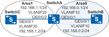
As shown in Figure 1, OSPF is running among three switches, and the entire OSPF network is partitioned into Area0 and Area1. It is required that restarting the OSPF process on SwitchC does not affect data forwarding.
Configuration Roadmap
The configuration roadmap is as follows:
Configure basic OSPF functions on each switch to implement basic connections on the OSPF network.
- Enable the Opaque LSA function on SwitchA and SwitchC so that OSPF supports OSPF GR through Type9 LSA.
- Configure the GR function on SwitchA and SwitchC so that data is forwarded properly when OSPF restarts.
Procedure
- Configure VLANs for interfaces.
# Configure SwitchA. The configurations of SwitchB and SwitchC are similar to the configuration of SwitchA.
<HUAWEI> system-view
[HUAWEI] sysname SwitchA
[SwitchA] vlan batch 10 20
[SwitchA] interface gigabitethernet 0/0/1
[SwitchA-GigabitEthernet0/0/1] port link-type trunk
[SwitchA-GigabitEthernet0/0/1] port trunk allow-pass vlan 10
[SwitchA-GigabitEthernet0/0/1] quit
[SwitchA] interface gigabitethernet 0/0/2
[SwitchA-GigabitEthernet0/0/2] port link-type trunk
[SwitchA-GigabitEthernet0/0/2] port trunk allow-pass vlan 20
[SwitchA-GigabitEthernet0/0/2] quit
- Configure an IP address for each VLANIF interface.
# Configure SwitchA. The configurations of SwitchB and SwitchC are similar to the configuration of SwitchA.
[SwitchA] interface vlanif 10
[SwitchA-Vlanif10] ip address 192.168.0.1 24
[SwitchA-Vlanif10] quit
[SwitchA] interface vlanif 20
[SwitchA-Vlanif20] ip address 192.168.1.1 24
[SwitchA-Vlanif20] quit
- Configure basic OSPF functions.
# Configure SwitchA.
[SwitchA] ospf 1 router-id 10.1.1.1
[SwitchA-ospf-1] area 0
[SwitchA-ospf-1-area-0.0.0.0] network 192.168.0.0 0.0.0.255
[SwitchA-ospf-1-area-0.0.0.0] quit
[SwitchA-ospf-1] area 1
[SwitchA-ospf-1-area-0.0.0.1] network 192.168.1.0 0.0.0.255
[SwitchA-ospf-1-area-0.0.0.1] quit
[SwitchA-ospf-1] quit
# Configure SwitchB.
[SwitchB] ospf 1 router-id 10.2.2.2
[SwitchB-ospf-1] area 0
[SwitchB-ospf-1-area-0.0.0.0] network 192.168.0.0 0.0.0.255
[SwitchB-ospf-1-area-0.0.0.0] quit
[SwitchB-ospf-1] quit
# Configure SwitchC.
[SwitchC] ospf 1 router-id 10.3.3.3
[SwitchC-ospf-1] area 1
[SwitchC-ospf-1-area-0.0.0.1] network 192.168.1.0 0.0.0.255
[SwitchC-ospf-1-area-0.0.0.1] quit
[SwitchC-ospf-1] quit
- Enable the Opaque LSA function.
# Configure SwitchA.
[SwitchA] ospf 1
[SwitchA-ospf-1] opaque-capability enable
[SwitchA-ospf-1] quit
# Configure SwitchC.
[SwitchC] ospf 1
[SwitchC-ospf-1] opaque-capability enable
[SwitchC-ospf-1] quit
- Configure the OSPF GR feature.
# Configure SwitchA.
[SwitchA] ospf 1
[SwitchA-ospf-1] graceful-restart
[SwitchA-ospf-1] return
# Configure SwitchC.
[SwitchC] ospf 1
[SwitchC-ospf-1] graceful-restart
[SwitchC-ospf-1] return
- Verify the configuration.
# Check the GR status of SwitchC.
<SwitchC> display ospf graceful-restart

          OSPF Process 1 with Router ID 10.3.3.3
 Graceful-restart capability     : enabled
 Graceful-restart support        : planned and un-planned, totally
 Helper-policy support           : planned and un-planned, strict lsa check
 Current GR state                : normal
 Graceful-restart period         : 120 seconds

 Number of neighbors under helper:
  Normal neighbors    : 0
  Virtual neighbors   : 0
  Sham-link neighbors : 0
  Total neighbors     : 0

 Number of restarting neighbors : 0

 Last exit reason:
  On graceful restart : none
  On Helper           : none
# Check the neighbor status on SwitchA.
<SwitchA> display ospf peer

	 OSPF Process 1 with Router ID 10.1.1.1
		 Neighbors

 Area 0.0.0.0 interface 192.168.0.1(Vlanif10)'s neighbors
 Router ID: 10.2.2.2          Address: 192.168.0.2      GR State: Normal
   State: Full  Mode:Nbr is  Master  Priority: 1
   DR: 192.168.0.2  BDR: 192.168.0.1  MTU: 0
   Dead timer due in 40  sec
   Retrans timer interval: 5
   Neighbor is up for 00:04:28
   Authentication Sequence: [ 0 ]

		 Neighbors

 Area 0.0.0.1 interface 192.168.1.1(Vlanif20)'s neighbors
 Router ID: 10.3.3.3          Address: 192.168.1.2      GR State: Normal
   State: Full  Mode:Nbr is  Master  Priority: 1
   DR: 192.168.1.1  BDR: 192.168.1.2  MTU: 0
   Dead timer due in 36  sec
   Retrans timer interval: 5
   Neighbor is up for 00:00:00
   Authentication Sequence: [ 0 ]
The preceding command output shows that the OSPF neighbor status of SwitchA is Full and GR status is Normal.
# Restart the OSPF process of SwitchC gracefully.
<SwitchC> reset ospf process graceful-restart# Check the neighbor status on SwitchA.
<SwitchA> display ospf peer

	 OSPF Process 1 with Router ID 10.1.1.1
		 Neighbors

 Area 0.0.0.0 interface 192.168.0.1(Vlanif10)'s neighbors
 Router ID: 10.2.2.2          Address: 192.168.0.2      GR State: Normal
   State: Full  Mode:Nbr is  Master  Priority: 1
   DR: 192.168.0.2  BDR: 192.168.0.1  MTU: 0
   Dead timer due in 40  sec
   Retrans timer interval: 5
   Neighbor is up for 00:04:28
   Authentication Sequence: [ 0 ]

		 Neighbors

 Area 0.0.0.1 interface 192.168.1.1(Vlanif20)'s neighbors
 Router ID: 10.3.3.3          Address: 192.168.1.2      GR State: Normal
   State: Full  Mode:Nbr is  Slave  Priority: 1
   DR: 192.168.1.1  BDR: 192.168.1.2  MTU: 0
   Dead timer due in 36  sec
   Retrans timer interval: 5
   Neighbor is up for 00:00:00
   Authentication Sequence: [ 0 ]
The preceding command output shows that the OSPF neighbor status of SwitchA and SwitchC are still Full without being affected by the graceful restart of the OSPF process on SwitchC.
Configuration Files
SwitchA configuration file
#
sysname SwitchA
#
vlan batch 10 20
#
interface Vlanif10
 ip address 192.168.0.1 255.255.255.0
#
interface Vlanif20
 ip address 192.168.1.1 255.255.255.0
#
interface GigabitEthernet0/0/1
 port link-type trunk
 port trunk allow-pass vlan 10
#
interface GigabitEthernet0/0/2
 port link-type trunk
 port trunk allow-pass vlan 20
#
ospf 1 router-id 10.1.1.1
 opaque-capability enable
 graceful-restart
 area 0.0.0.0
  network 192.168.0.0 0.0.0.255
 area 0.0.0.1
  network 192.168.1.0 0.0.0.255
#
return
SwitchB configuration file
#
sysname SwitchB
#
vlan batch 10
#
interface Vlanif10
 ip address 192.168.0.2 255.255.255.0
#
interface GigabitEthernet0/0/1
 port link-type trunk
 port trunk allow-pass vlan 10
#
ospf 1 router-id 10.2.2.2
 area 0.0.0.0
  network 192.168.0.0 0.0.0.255
#
return
SwitchC configuration file
#
sysname SwitchC
#
vlan batch 20
#
interface Vlanif20
 ip address 192.168.1.2 255.255.255.0
#
interface GigabitEthernet0/0/1
 port link-type trunk
 port trunk allow-pass vlan 20
#
ospf 1 router-id 10.3.3.3
 opaque-capability enable
 graceful-restart
 area 0.0.0.1
  network 192.168.1.0 0.0.0.255
#
return