Example for Configuring a Hybrid SEP+MSTP Ring Network
Networking Requirements
Generally, redundant links are used to connect an Ethernet switching network to an upper-layer network to provide link backup and enhance network reliability. The use of redundant links, however, may produce loops, causing broadcast storms and rendering the MAC address table unstable. As a result, communication quality deteriorates, and services may even be interrupted. SEP can be deployed on the ring network to eliminate loops and restore communication if a link fault occurs.

In this example, devices at the aggregation layer run the MSTP protocol.
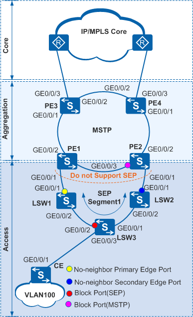
In Figure 1, multiple Layer 2 switching devices form a ring at the access layer, and multiple Layer 3 devices form a ring at the aggregation layer. The two devices where the access layer and the aggregation layer are intersected do not support SEP. You can configure SEP at the access layer to implement redundancy protection switching and configure the topology change notification function on an edge device in a SEP segment. This function enables an upper-layer network to detect topology changes in a lower-layer network in time.
- When there is no faulty link on the ring network, SEP can eliminate loops.
- When a link fails on the ring network, SEP can rapidly restore communication between nodes.
- The topology change notification function must be configured on an edge device in a SEP segment. This enables an upper-layer network to detect topology changes in a lower-layer network in time.
After receiving a message indicating the topology change in a lower-layer network, a device on an upper-layer network sends TC packets to instruct other devices to delete original MAC addresses and learn new MAC addresses after the topology of the lower-layer network changes. This ensures uninterrupted traffic forwarding.
Configuration Roadmap
The configuration roadmap is as follows:
Configure basic SEP functions.
Configure SEP segment 1 on LSW1 to LSW3 and configure VLAN 10 as the control VLAN of SEP segment 1.
Add LSW1 to LSW3 to SEP segment 1 and configure interface roles on the edge devices (LSW1 and LSW2) of the SEP segment.
PE1 and PE2 do not support the SEP protocol; therefore, the interfaces of LSW1 and LSW2 connected to the PEs must be no-neighbor edge interfaces.
On the device where the no-neighbor primary edge interface is located, specify the interface in the middle of the SEP segment as the interface to block.
Configure manual preemption.
Configure the topology change notification function so that the upper-layer network running MSTP can be notified of topology changes in the SEP segment.
Configure basic MSTP functions.
Add LSW1, LSW2, PE1 to PE4 to an MST region RG1.
Create VLANs on LSW1, LSW2, PE1 to PE4 and add interfaces on the STP ring to the VLANs.
Configure PE3 as the root bridge and PE4 as the backup root bridge.
Configure the Layer 2 forwarding function on CE and LSW1 to LSW3.
Procedure
- Configure basic SEP functions.
Configure SEP segment 1 on LSW1 to LSW3 and configure VLAN 10 as the control VLAN of SEP segment 1.
# Configure LSW1.<HUAWEI> system-view [HUAWEI] sysname LSW1 [LSW1] sep segment 1 [LSW1-sep-segment1] control-vlan 10 [LSW1-sep-segment1] protected-instance all [LSW1-sep-segment1] quit
# Configure LSW2.<HUAWEI> system-view [HUAWEI] sysname LSW2 [LSW2] sep segment 1 [LSW2-sep-segment1] control-vlan 10 [LSW2-sep-segment1] protected-instance all [LSW2-sep-segment1] quit
# Configure LSW3.<HUAWEI> system-view [HUAWEI] sysname LSW3 [LSW3] sep segment 1 [LSW3-sep-segment1] control-vlan 10 [LSW3-sep-segment1] protected-instance all [LSW3-sep-segment1] quit
The control VLAN must be a VLAN that has not been created or used, but the configuration file automatically displays the command for creating the VLAN.
Each SEP segment must be configured with a control VLAN. After an interface is added to a SEP segment configured with a control VLAN, the interface will be automatically added to the control VLAN.
Add LSW1 to LSW3 to SEP segment 1 and configure interface roles.
By default, STP is enabled on a Layer 2 interface. Before adding an interface to a SEP segment, disable STP on the interface.
# Configure LSW1.
[LSW1] interface gigabitethernet 0/0/1
[LSW1-GigabitEthernet0/0/1] port link-type hybrid
[LSW1-GigabitEthernet0/0/1] sep segment 1 edge no-neighbor primary
[LSW1-GigabitEthernet0/0/1] quit
[LSW1] interface gigabitethernet 0/0/2
[LSW1-GigabitEthernet0/0/2] port link-type hybrid
[LSW1-GigabitEthernet0/0/2] stp disable
[LSW1-GigabitEthernet0/0/2] sep segment 1
[LSW1-GigabitEthernet0/0/2] quit
# Configure LSW2.
[LSW2] interface gigabitethernet 0/0/1
[LSW2-GigabitEthernet0/0/1] port link-type hybrid
[LSW2-GigabitEthernet0/0/1] sep segment 1 edge no-neighbor secondary
[LSW2-GigabitEthernet0/0/1] quit
[LSW2] interface gigabitethernet 0/0/2
[LSW2-GigabitEthernet0/0/2] port link-type hybrid
[LSW2-GigabitEthernet0/0/2] stp disable
[LSW2-GigabitEthernet0/0/2] sep segment 1
[LSW2-GigabitEthernet0/0/2] quit
# Configure LSW3.
[LSW3] interface gigabitethernet 0/0/1
[LSW3-GigabitEthernet0/0/1] port link-type hybrid
[LSW3-GigabitEthernet0/0/1] stp disable
[LSW3-GigabitEthernet0/0/1] sep segment 1
[LSW3-GigabitEthernet0/0/1] quit
[LSW3] interface gigabitethernet 0/0/2
[LSW3-GigabitEthernet0/0/2] port link-type hybrid
[LSW3-GigabitEthernet0/0/2] stp disable
[LSW3-GigabitEthernet0/0/2] sep segment 1
[LSW3-GigabitEthernet0/0/2] quit
Specify an interface to block.
# On LSW1 where the no-neighbor primary edge interface of SEP segment 1 is located, specify the interface in the middle of the SEP segment as the interface to block.
[LSW1] sep segment 1
[LSW1-sep-segment1] block port middle
Configure the preemption mode.
# Configure the manual preemption mode on LSW1.
[LSW1-sep-segment1] preempt manualConfigure the topology change notification function.
# Configure devices in SEP segment 1 to notify the MSTP network of topology changes.
# Configure LSW1.
[LSW1-sep-segment1] tc-notify stp
[LSW1-sep-segment1] quit
# Configure LSW2.
[LSW2] sep segment 1
[LSW2-sep-segment1] tc-notify stp
[LSW2-sep-segment1] quit
- Configure basic MSTP functions.
Configure an MST region.
# Configure PE1.
<HUAWEI> system-view
[HUAWEI] sysname PE1
[PE1] stp region-configuration
[PE1-mst-region] region-name RG1
[PE1-mst-region] active region-configuration
[PE1-mst-region] quit
# Configure PE2.
<HUAWEI> system-view
[HUAWEI] sysname PE2
[PE2] stp region-configuration
[PE2-mst-region] region-name RG1
[PE2-mst-region] active region-configuration
[PE2-mst-region] quit
# Configure PE3.
<HUAWEI> system-view
[HUAWEI] sysname PE3
[PE3] stp region-configuration
[PE3-mst-region] region-name RG1
[PE3-mst-region] active region-configuration
[PE3-mst-region] quit
# Configure PE4.
<HUAWEI> system-view
[HUAWEI] sysname PE4
[PE4] stp region-configuration
[PE4-mst-region] region-name RG1
[PE4-mst-region] active region-configuration
[PE4-mst-region] quit
# Configure LSW1.
[LSW1] stp region-configuration
[LSW1-mst-region] region-name RG1
[LSW1-mst-region] active region-configuration
[LSW1-mst-region] quit
# Configure LSW2.
[LSW2] stp region-configuration
[LSW2-mst-region] region-name RG1
[LSW2-mst-region] active region-configuration
[LSW2-mst-region] quit
Create VLANs and add interfaces to VLANs.
# On PE1, create VLAN 100 and add GE0/0/1, GE0/0/2, and GE0/0/3 to VLAN 100.
[PE1] vlan 100
[PE1-vlan100] quit
[PE1] interface gigabitethernet 0/0/1
[PE1-GigabitEthernet0/0/1] port link-type hybrid
[PE1-GigabitEthernet0/0/1] port hybrid tagged vlan 100
[PE1-GigabitEthernet0/0/1] quit
[PE1] interface gigabitethernet 0/0/2
[PE1-GigabitEthernet0/0/2] port link-type hybrid
[PE1-GigabitEthernet0/0/2] port hybrid tagged vlan 100
[PE1-GigabitEthernet0/0/2] quit
[PE1] interface gigabitethernet 0/0/3
[PE1-GigabitEthernet0/0/3] port link-type hybrid
[PE1-GigabitEthernet0/0/3] port hybrid tagged vlan 100
[PE1-GigabitEthernet0/0/3] quit
# On PE2, PE3, and PE4, create VLAN 100 and add GE0/0/1, GE0/0/2, and GE0/0/3 to VLAN 100.
The configurations of PE2, PE3, and PE4 are similar to the configuration of PE1. For details about the configuration, see the configuration files.
# On LSW1 and LSW2, create VLAN 100 and add GE0/0/1 to VLAN 100. The configurations of LSW1 and LSW2 are similar to the configuration of PE1. For details about the configuration, see the configuration files.
Enable MSTP.
# Configure PE1.
[PE1] stp enable
# Configure PE2.
[PE2] stp enable
# Configure PE3.
[PE3] stp enable
# Configure PE4.
[PE4] stp enable
# Configure LSW1.
[LSW1] stp enable# Configure LSW2.
[LSW2] stp enableConfigure PE3 as the root bridge and PE4 as the backup root bridge.
# Set the priority of PE3 to 0 in MSTI0 to ensure that PE3 functions as the root bridge.
[PE3] stp root primary
# Set the priority of PE4 to 4096 in MSTI0 to ensure that PE4 functions as the backup root bridge.
[PE4] stp root secondary
- Configure the Layer 2 forwarding function on the CE and LSW1 to LSW3.
For details about the configuration, see the configuration files.
- Verify the configuration.
After the configurations are complete and network becomes stable, run the following commands to verify the configuration. LSW1 is used as an example.
Run the shutdown command on GE0/0/1 of LSW2 to simulate an interface fault, and then run the display sep interface command on LSW3 to check whether GE0/0/2 of LSW3 has switched from the Discarding state to the Forwarding state.
<LSW3> display sep interface gigabitethernet 0/0/2
SEP segment 1
----------------------------------------------------------------
Interface           Port Role     Neighbor Status     Port Status
----------------------------------------------------------------
GE0/0/2             common        up                  forwarding
Configuration Files
LSW1 configuration file
#
sysname LSW1
#
vlan batch 10 100
#
stp region-configuration
 region-name RG1
 active region-configuration
#
sep segment 1
 control-vlan 10
 block port middle
 tc-notify stp
 protected-instance 0 to 48
#
interface GigabitEthernet0/0/1
 port link-type hybrid
 port hybrid tagged vlan 10 100
 sep segment 1 edge no-neighbor primary
#
interface GigabitEthernet0/0/2
 port link-type hybrid
 port hybrid tagged vlan 10 100
 stp disable
 sep segment 1
#
return
LSW2 configuration file
#
 sysname LSW2
#
 vlan batch 10 100
#
stp region-configuration
 region-name RG1
 active region-configuration
#
sep segment 1
 control-vlan 10
 tc-notify stp
 protected-instance 0 to 48
#
interface GigabitEthernet0/0/1
 port link-type hybrid
 port hybrid tagged vlan 10 100
 sep segment 1 edge no-neighbor secondary
#
interface GigabitEthernet0/0/2
 port link-type hybrid
 port hybrid tagged vlan 10 100
 stp disable
 sep segment 1
#
return
LSW3 configuration file
#
 sysname LSW3
#
 vlan batch 10 100
#
sep segment 1
 control-vlan 10
 protected-instance 0 to 48
#
interface GigabitEthernet0/0/1
 port link-type hybrid
 port hybrid tagged vlan 10 100
 stp disable
 sep segment 1
#
interface GigabitEthernet0/0/2
 port link-type hybrid
 port hybrid tagged vlan 10 100
 stp disable
 sep segment 1
#
interface GigabitEthernet0/0/3
 port link-type hybrid
 port hybrid tagged vlan vlan 100
#
return
PE1 configuration file
#
 sysname PE1
#
 vlan batch 100
#
 stp region-configuration
  region-name RG1
  active region-configuration
#
interface GigabitEthernet0/0/1
 port link-type hybrid
 port hybrid tagged vlan 100
#
interface GigabitEthernet0/0/2
 port link-type hybrid
 port hybrid tagged vlan 100
#
interface GigabitEthernet0/0/3
 port link-type hybrid
 port hybrid tagged vlan 100
#
return
PE2 configuration file
#
 sysname PE2
#
 vlan batch 100
#
 stp region-configuration
  region-name RG1
  active region-configuration
#
interface GigabitEthernet0/0/1
 port link-type hybrid
 port hybrid tagged vlan 100
#
interface GigabitEthernet0/0/2
 port link-type hybrid
 port hybrid tagged vlan 100
#
interface GigabitEthernet0/0/3
 port link-type hybrid
 port hybrid tagged vlan 100
#
return
PE3 configuration file
#
 sysname PE3
#
 vlan batch 100 200
#
 stp instance 0 root primary
#
 stp region-configuration
  region-name RG1
  active region-configuration
#
interface GigabitEthernet0/0/1
 port link-type hybrid
 port hybrid tagged vlan 100
#
interface GigabitEthernet0/0/2
 port link-type hybrid
 port hybrid tagged vlan 100 200
#
interface GigabitEthernet0/0/3
 port link-type hybrid
 port hybrid pvid vlan 200
 port hybrid tagged vlan 100
 port hybrid untagged vlan 200
#
return
PE4 configuration file
#
 sysname PE4
#
 vlan batch 100 200
#
 stp instance 0 root secondary
#
 stp region-configuration
  region-name RG1
  active region-configuration
#
interface GigabitEthernet0/0/1
 port link-type hybrid
 port hybrid tagged vlan 100
#
interface GigabitEthernet0/0/2
 port link-type hybrid
 port hybrid tagged vlan 100 200
#
interface GigabitEthernet0/0/3
 port link-type hybrid
 port hybrid pvid vlan 200
 port hybrid tagged vlan 100
 port hybrid untagged vlan 200
#
return
- CE configuration file
#
 sysname CE
#
 vlan batch 100
#
interface GigabitEthernet0/0/1
 port link-type hybrid
 port hybrid tagged vlan 100
#
return