Example for Configuring MSTP and VRRP
Overview
When VRRP is deployed on a network, multiple devices transmit services simultaneously. Each virtual device consists of one master and several backups. If redundant links need to be deployed for access backup, MSTP needs to be deployed to eliminate loops and ensure load balancing of traffic.
Configuration Notes
For applicable product models and versions, see Applicable Product Models and Versions.

For details about software mappings, visit Hardware Query Tool and search for the desired product model.
- The ports connected to terminals do not participate in MSTP calculation. Therefore, configure the ports as edge ports or disable STP on the ports.
Networking Requirements
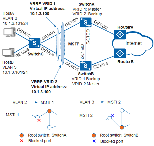
In Figure 1, hosts connect to the network through SwitchC. SwitchC is dual-homed to SwitchA and SwitchB and connects to the Internet. Redundant links are deployed for access backup. The use of redundant links, however, may produce loops, causing broadcast storms and rendering the MAC address table unstable.
It is required that network loops be prevented when redundant links are deployed, traffic be switched to another link when one link is disconnected, and network bandwidth be effectively used.
MSTP can be configured on the network. MSTP blocks redundant links and prunes a network into a tree topology free from loops. VRRP can be configured on SwitchA and SwitchB. HostA connects to the Internet with SwitchA as the default gateway and SwitchB as the backup gateway; HostB connects to the Internet with SwitchB as the default gateway and SwitchA as the backup gateway. This setting implements reliability and traffic load balancing.
Device |
Interface |
VLANIF Interface |
IP Address |
|---|---|---|---|
SwitchA |
GE1/0/1 and GE1/0/2 |
VLANIF 2 |
10.1.2.102/24 |
GE1/0/1 and GE1/0/2 |
VLANIF 3 |
10.1.3.102/24 |
|
GE1/0/3 |
VLANIF 4 |
10.1.4.102/24 |
|
SwitchB |
GE1/0/1 and GE1/0/2 |
VLANIF 2 |
10.1.2.103/24 |
GE1/0/1 and GE1/0/2 |
VLANIF 3 |
10.1.3.103/24 |
|
GE1/0/3 |
VLANIF 5 |
10.1.5.103/24 |
Configuration Roadmap
The configuration roadmap is as follows:
- Configure basic MSTP functions on switching devices of the ring network.
Configure an MST region and create multi-instance, and map VLAN 2 to MSTI 1 and VLAN 3 to MSTI 2 to load balance traffic.
Configure the root bridge and secondary root bridge in each MST region.
Configure the path cost of a port in each MSTI so that the port can be blocked.
- Enable MSTP to prevent loops.
Enable MSTP globally.
Enable MSTP on all ports except the ports connected to hosts.
Enable protection functions to protect devices or links. For example, enable root protection on the designed port of the root bridge in each MSTI.
Configure Layer 2 forwarding on devices.
- Assign an IP address to each interface and configure a routing
protocol to ensure network connectivity. In this example, SwitchA and SwitchB need to support VRRP and OSPF. For details about the models supporting VRRP and OSPF, see the documentation.
- Create VRRP groups 1 and 2 on SwitchA and SwitchB. In VRRP group 1, configure SwitchA as the master and SwitchB as the backup. In VRRP group 2, configure SwitchB as the master and SwitchA as the backup.
Procedure
- Configure basic MSTP functions.
Configure SwitchA, SwitchB, and SwitchC in the MST region RG1 and create MSTI 1 and MSTI 2.
# Configure an MST region on SwitchA.
<HUAWEI> system-view
[HUAWEI] sysname SwitchA
[SwitchA] stp region-configuration //Enter the MST region view.
[SwitchA-mst-region] region-name RG1 //Configure the region name as RG1.
[SwitchA-mst-region] instance 1 vlan 2 //Maps VLAN 2 to MSTI 1.
[SwitchA-mst-region] instance 2 vlan 3 //Maps VLAN 3 to MSTI 2.
[SwitchA-mst-region] active region-configuration //Activate the MST region configuration.
[SwitchA-mst-region] quit
# Configure an MST region on SwitchB.
<HUAWEI> system-view
[HUAWEI] sysname SwitchB
[SwitchB] stp region-configuration //Enter the MST region view.
[SwitchB-mst-region] region-name RG1 //Configure the region name as RG1.
[SwitchB-mst-region] instance 1 vlan 2 //Maps VLAN 2 to MSTI 1.
[SwitchB-mst-region] instance 2 vlan 3 //Maps VLAN 3 to MSTI 2.
[SwitchB-mst-region] active region-configuration //Activate the MST region configuration.
[SwitchB-mst-region] quit
# Configure an MST region on SwitchC.
<HUAWEI> system-view
[HUAWEI] sysname SwitchC
[SwitchC] stp region-configuration //Enter the MST region view.
[SwitchC-mst-region] region-name RG1 //Configure the region name as RG1.
[SwitchC-mst-region] instance 1 vlan 2 //Maps VLAN 2 to MSTI 1.
[SwitchC-mst-region] instance 2 vlan 3 //Maps VLAN 3 to MSTI 2.
[SwitchC-mst-region] active region-configuration //Activate the MST region configuration.
[SwitchC-mst-region] quit
Configure root bridges and secondary root bridges of MSTI 1 and MSTI 2 in the MST region RG1.
Configure the root bridge and secondary root bridge in MSTI 1.
# Configure SwitchA as the root bridge in MSTI 1.
[SwitchA] stp instance 1 root primary
# Configure SwitchB as the secondary root bridge in MSTI 1.
[SwitchB] stp instance 1 root secondary
Configure the root bridge and secondary root bridge in MSTI 2.
# Configure SwitchB as the root bridge in MSTI 2.
[SwitchB] stp instance 2 root primary
# Configure SwitchA as the secondary root bridge in MSTI 2.
[SwitchA] stp instance 2 root secondary
Set the path costs of the ports to be blocked in MSTI 1 and MSTI 2 to be larger than the default values.
The path cost range depends on the algorithm. Huawei's proprietary algorithm is used as an example. Set the path costs of the ports to be blocked in MSTI 1 and MSTI 2 to 20000.
Switching devices on the same network must use the same algorithm to calculate the path cost of ports.
# Configure SwitchA to use Huawei's proprietary algorithm to calculate the path cost.
[SwitchA] stp pathcost-standard legacy
# Configure SwitchB to use Huawei's proprietary algorithm to calculate the path cost.
[SwitchB] stp pathcost-standard legacy
# Configure SwitchC to use Huawei's proprietary algorithm to calculate the path cost, and set the path cost of GE1/0/1 in MSTI 2 to 20000 and path cost of GE1/0/4 in MSTI 1 to 20000.
[SwitchC] stp pathcost-standard legacy
[SwitchC] interface gigabitethernet 1/0/1
[SwitchC-GigabitEthernet1/0/1] stp instance 2 cost 20000
[SwitchC-GigabitEthernet1/0/1] quit
[SwitchC] interface gigabitethernet 1/0/4
[SwitchC-GigabitEthernet1/0/4] stp instance 1 cost 20000
[SwitchC-GigabitEthernet1/0/4] quit
Enable MSTP to eliminate loops.
Enable MSTP globally on devices.
# Enable MSTP on SwitchA.
[SwitchA] stp enable
# Enable MSTP on SwitchB.
[SwitchB] stp enable
# Enable MSTP on SwitchC.
[SwitchC] stp enable
Configure the ports connected to hosts as edge ports.
[SwitchC] interface gigabitethernet 1/0/2
[SwitchC-GigabitEthernet1/0/2] stp edged-port enable
[SwitchC-GigabitEthernet1/0/2] quit
[SwitchC] interface gigabitethernet 1/0/3
[SwitchC-GigabitEthernet1/0/3] stp edged-port enable
[SwitchC-GigabitEthernet1/0/3] quit
(Optional) Configure BPDU protection on SwitchC.
[SwitchC] stp bpdu-protection
Configure the ports connected to the router as edge ports.
# Configure the SwitchA.
[SwitchA] interface gigabitethernet 1/0/3
[SwitchA-GigabitEthernet1/0/3] stp edged-port enable
[SwitchA-GigabitEthernet1/0/3] quit
(Optional) Configure BPDU protection on SwitchA.
[SwitchA] stp bpdu-protection
# Configure the SwitchB.
[SwitchB] interface gigabitethernet 1/0/3
[SwitchB-GigabitEthernet1/0/3] stp edged-port enable
[SwitchB-GigabitEthernet1/0/3] quit
(Optional) Configure BPDU protection on SwitchB.
[SwitchB] stp bpdu-protection
If edge ports are connected to network devices that have STP enabled and BPDU protection is enabled, the edge ports will be shut down and their attributes remain unchanged after they receive BPDUs.
- Enable protection functions. For example, enable root protection
on the designed port of the root bridge in each MSTI.
# Enable root protection on GE1/0/1 of SwitchA.
[SwitchA] interface gigabitethernet 1/0/1
[SwitchA-GigabitEthernet1/0/1] stp root-protection
[SwitchA-GigabitEthernet1/0/1] quit
# Enable root protection on GE1/0/1 of SwitchB.
[SwitchB] interface gigabitethernet 1/0/1
[SwitchB-GigabitEthernet1/0/1] stp root-protection
[SwitchB-GigabitEthernet1/0/1] quit
- Configure Layer 2 forwarding on switches of the ring network.
Create VLAN 2 and VLAN 3 on SwitchA, SwitchB, and SwitchC.
# Create VLAN 2 and VLAN 3 on SwitchA.
[SwitchA] vlan batch 2 to 3
# Create VLAN 2 and VLAN 3 on SwitchB.
[SwitchB] vlan batch 2 to 3
# Create VLAN 2 and VLAN 3 on SwitchC.
[SwitchC] vlan batch 2 to 3
Add ports connected to the ring to VLANs.
# Add GE1/0/1 on SwitchA to VLANs.
[SwitchA] interface gigabitethernet 1/0/1
[SwitchA-GigabitEthernet1/0/1] port link-type trunk
[SwitchA-GigabitEthernet1/0/1] port trunk allow-pass vlan 2 to 3
[SwitchA-GigabitEthernet1/0/1] quit
# Add GE1/0/2 on SwitchA to VLANs.
[SwitchA] interface gigabitethernet 1/0/2
[SwitchA-GigabitEthernet1/0/2] port link-type trunk
[SwitchA-GigabitEthernet1/0/2] port trunk allow-pass vlan 2 to 3
[SwitchA-GigabitEthernet1/0/2] quit
# Add GE1/0/1 on SwitchB to VLANs.
[SwitchB] interface gigabitethernet 1/0/1
[SwitchB-GigabitEthernet1/0/1] port link-type trunk
[SwitchB-GigabitEthernet1/0/1] port trunk allow-pass vlan 2 to 3
[SwitchB-GigabitEthernet1/0/1] quit
# Add GE1/0/2 on SwitchB to VLANs.
[SwitchB] interface gigabitethernet 1/0/2
[SwitchB-GigabitEthernet1/0/2] port link-type trunk
[SwitchB-GigabitEthernet1/0/2] port trunk allow-pass vlan 2 to 3
[SwitchB-GigabitEthernet1/0/2] quit
# Add GE1/0/1 on SwitchC to VLANs.
[SwitchC] interface gigabitethernet 1/0/1
[SwitchC-GigabitEthernet1/0/1] port link-type trunk
[SwitchC-GigabitEthernet1/0/1] port trunk allow-pass vlan 2 to 3
[SwitchC-GigabitEthernet1/0/1] quit
# Add GE1/0/2 on SwitchC to VLANs.
[SwitchC] interface gigabitethernet 1/0/2
[SwitchC-GigabitEthernet1/0/2] port link-type access
[SwitchC-GigabitEthernet1/0/2] port default vlan 2
[SwitchC-GigabitEthernet1/0/2] quit
# Add GE1/0/3 on SwitchC to VLANs.
[SwitchC] interface gigabitethernet 1/0/3
[SwitchC-GigabitEthernet1/0/3] port link-type access
[SwitchC-GigabitEthernet1/0/3] port default vlan 3
[SwitchC-GigabitEthernet1/0/3] quit
# Add GE1/0/4 on SwitchC to VLANs.
[SwitchC] interface gigabitethernet 1/0/4
[SwitchC-GigabitEthernet1/0/4] port link-type trunk
[SwitchC-GigabitEthernet1/0/4] port trunk allow-pass vlan 2 to 3
[SwitchC-GigabitEthernet1/0/4] quit
- Verify the configuration.
After the configuration is complete and the network topology becomes stable, perform the following operations to verify the configuration.
MSTI 1 and MSTI 2 are used as examples, so you do not need to check the port status in MSTI 0.
# Run the display stp brief command on SwitchA to view the port status and protection type. The displayed information is as follows:
[SwitchA] display stp brief
 MSTID      Port                        Role  STP State       Protection
   0        GigabitEthernet1/0/1        DESI  FORWARDING      ROOT
   0        GigabitEthernet1/0/2        DESI  FORWARDING      NONE
   1        GigabitEthernet1/0/1        DESI  FORWARDING      ROOT
   1        GigabitEthernet1/0/2        DESI  FORWARDING      NONE
   2        GigabitEthernet1/0/1        DESI  FORWARDING      ROOT
   2        GigabitEthernet1/0/2        ROOT  FORWARDING      NONE
In MSTI 1, GE1/0/2 and GE1/0/1 on SwitchA are designed ports because SwitchA is the root bridge. In MSTI 2, GE1/0/1 on SwitchA is the designed port and GE1/0/2 is the root port.
# Run the display stp brief command on SwitchB. The displayed information is as follows:
[SwitchB] display stp brief
 MSTID      Port                        Role  STP State       Protection
   0        GigabitEthernet1/0/1        DESI  FORWARDING      ROOT
   0        GigabitEthernet1/0/2        ROOT  FORWARDING      NONE
   1        GigabitEthernet1/0/1        DESI  FORWARDING      ROOT
   1        GigabitEthernet1/0/2        ROOT  FORWARDING      NONE
   2        GigabitEthernet1/0/1        DESI  FORWARDING      ROOT
   2        GigabitEthernet1/0/2        DESI  FORWARDING      NONE
In MSTI 2, GE1/0/1 and GE1/0/2 on SwitchB are designed ports because SwitchB is the root bridge. In MSTI 1, GE1/0/1 on SwitchB is the designed port and GE1/0/2 is the root port.
# Run the display stp interface brief command on SwitchC. The displayed information is as follows:
[SwitchC] display stp interface gigabitethernet 1/0/1 brief
 MSTID      Port                        Role  STP State       Protection
   0        GigabitEthernet1/0/1        ROOT  FORWARDING      NONE
   1        GigabitEthernet1/0/1        ROOT  FORWARDING      NONE
   2        GigabitEthernet1/0/1        ALTE  DISCARDING      NONE
[SwitchC] display stp interface gigabitethernet 1/0/4 brief
 MSTID      Port                        Role  STP State       Protection
   0        GigabitEthernet1/0/4        ALTE  DISCARDING      NONE
   1        GigabitEthernet1/0/4        ALTE  DISCARDING      NONE
   2        GigabitEthernet1/0/4        ROOT  FORWARDING      NONE
GE1/0/1 on SwitchC is the root port in MSTI 1 and is blocked in MSTI 2. GE1/0/4 on SwitchC is blocked in MSTI 1 and is the designated port in MSTI 2.
- Configure devices to ensure network connectivity.
# Assign an IP address to each interface. SwitchA is used as an example. The configuration of SwitchB is similar to that of SwitchA, and is not mentioned here. For details, see the configuration files.
[SwitchA] vlan batch 4
[SwitchA] interface gigabitethernet 1/0/3
[SwitchA-GigabitEthernet1/0/3] port link-type trunk
[SwitchA-GigabitEthernet1/0/3] port trunk allow-pass vlan 4
[SwitchA-GigabitEthernet1/0/3] quit
[SwitchA] interface vlanif 2
[SwitchA-Vlanif2] ip address 10.1.2.102 24
[SwitchA-Vlanif2] quit
[SwitchA] interface vlanif 3
[SwitchA-Vlanif3] ip address 10.1.3.102 24
[SwitchA-Vlanif3] quit
[SwitchA] interface vlanif 4
[SwitchA-Vlanif4] ip address 10.1.4.102 24
[SwitchA-Vlanif4] quit
# Configure OSPF between SwitchA, SwitchB, and router. SwitchA is used as an example. The configuration of SwitchB is similar to that of SwitchA, and is not mentioned here. For details, see the configuration files.
[SwitchA] ospf 1
[SwitchA-ospf-1] area 0
[SwitchA-ospf-1-area-0.0.0.0] network 10.1.2.0 0.0.0.255
[SwitchA-ospf-1-area-0.0.0.0] network 10.1.3.0 0.0.0.255
[SwitchA-ospf-1-area-0.0.0.0] network 10.1.4.0 0.0.0.255
[SwitchA-ospf-1-area-0.0.0.0] quit
[SwitchA-ospf-1] quit
- Configure VRRP groups.
# Configure VRRP group 1 on SwitchA and SwitchB, set the priority of SwitchA to 120 and the preemption delay to 20s, and set the default priority for SwitchB.
[SwitchA] interface vlanif 2
[SwitchA-Vlanif2] vrrp vrid 1 virtual-ip 10.1.2.100 //Create VRRP group 1 and set the virtual IP address to 10.1.2.100.
[SwitchA-Vlanif2] vrrp vrid 1 priority 120 //Set the priority of VRRP group 1 to 120.
[SwitchA-Vlanif2] vrrp vrid 1 preempt-mode timer delay 20 //Set the preemption delay of VRRP group 1 to 20s.
[SwitchA-Vlanif2] quit
[SwitchB] interface vlanif 2
[SwitchB-Vlanif2] vrrp vrid 1 virtual-ip 10.1.2.100 //Create VRRP group 1 and set the virtual IP address to 10.1.2.100.
[SwitchB-Vlanif2] quit
# Configure VRRP group 2 on SwitchA and SwitchB, set the priority of SwitchB to 120 and the preemption delay to 20s, and set the default priority for SwitchA.
[SwitchB] interface vlanif 3
[SwitchB-Vlanif3] vrrp vrid 2 virtual-ip 10.1.3.100 //Create VRRP group 2 and set the virtual IP address to 10.1.3.100.
[SwitchB-Vlanif3] vrrp vrid 2 priority 120 //Set the priority of VRRP group 2 to 120.
[SwitchB-Vlanif3] vrrp vrid 2 preempt-mode timer delay 20 //Set the preemption delay of VRRP group 2 to 20s.
[SwitchB-Vlanif3] quit
[SwitchA] interface vlanif 3
[SwitchA-Vlanif3] vrrp vrid 2 virtual-ip 10.1.3.100 //Create VRRP group 2 and set the virtual IP address to 10.1.3.100.
[SwitchA-Vlanif3] quit
# Set virtual IP address 10.1.2.100 of VRRP group 1 as the default gateway of HostA, and virtual IP address 10.1.3.100 of VRRP group 2 as the default gateway of HostB.
- Verify the configuration.
# After the configuration is complete, run the display vrrp command on SwitchA. The following output shows that SwitchA is the master in VRRP group 1 and the backup in VRRP group 2.
[SwitchA] display vrrp
  Vlanif2 | Virtual Router 1
    State : Master
    Virtual IP : 10.1.2.100
    Master IP : 10.1.2.102
    PriorityRun : 120
    PriorityConfig : 120
    MasterPriority : 120
    Preempt : YES   Delay Time : 20 s
    TimerRun : 1 s
    TimerConfig : 1 s
    Auth type : NONE
    Virtual MAC : 0000-5e00-0101
    Check TTL : YES
    Config type : normal-vrrp
    Backup-forward : disabled
    Create time : 2012-05-11 11:39:18
    Last change time : 2012-05-26 11:38:58

  Vlanif3 | Virtual Router 2
    State : Backup
    Virtual IP : 10.1.3.100
    Master IP : 10.1.3.103
    PriorityRun : 100
    PriorityConfig : 100
    MasterPriority : 120
    Preempt : YES   Delay Time : 0 s
    TimerRun : 1 s
    TimerConfig : 1 s
    Auth type : NONE
    Virtual MAC : 0000-5e00-0102
    Check TTL : YES
    Config type : normal-vrrp
    Backup-forward : disabled
    Create time : 2012-05-11 11:40:18
    Last change time : 2012-05-26 11:48:58
# After the configuration is complete, run the display vrrp command on SwitchB. The following output shows that SwitchB is the backup in VRRP group 1 and the master in VRRP group 2.
[SwitchB] display vrrp
  Vlanif2 | Virtual Router 1
    State : Backup
    Virtual IP : 10.1.2.100
    Master IP : 10.1.2.102
    PriorityRun : 100
    PriorityConfig : 100
    MasterPriority : 120
    Preempt : YES   Delay Time : 0 s
    TimerRun : 1 s
    TimerConfig : 1 s
    Auth type : NONE
    Virtual MAC : 0000-5e00-0101
    Check TTL : YES
    Config type : normal-vrrp
    Backup-forward : disabled
    Create time : 2012-05-11 11:39:18
    Last change time : 2012-05-26 11:38:58

  Vlanif3 | Virtual Router 2
    State : Master
    Virtual IP : 10.1.3.100
    Master IP : 10.1.3.103
    PriorityRun : 120
    PriorityConfig : 120
    MasterPriority : 120
    Preempt : YES   Delay Time : 20 s
    TimerRun : 1 s
    TimerConfig : 1 s
    Auth type : NONE
    Virtual MAC : 0000-5e00-0102
    Check TTL : YES
    Config type : normal-vrrp
    Backup-forward : disabled
    Create time : 2012-05-11 11:40:18
    Last change time : 2012-05-26 11:48:58
Configuration Files
SwitchA configuration file
#
sysname SwitchA
#
vlan batch 2 to 4
#
stp instance 1 root primary
stp instance 2 root secondary
stp bpdu-protection
stp pathcost-standard legacy
#
stp region-configuration
 region-name RG1
 instance 1 vlan 2
 instance 2 vlan 3
 active region-configuration
#
interface Vlanif2
 ip address 10.1.2.102 255.255.255.0
 vrrp vrid 1 virtual-ip 10.1.2.100
 vrrp vrid 1 priority 120
 vrrp vrid 1 preempt-mode timer delay 20
#
interface Vlanif3
 ip address 10.1.3.102 255.255.255.0
 vrrp vrid 2 virtual-ip 10.1.3.100
#
interface Vlanif4
 ip address 10.1.4.102 255.255.255.0
 #
interface GigabitEthernet1/0/1
 port link-type trunk
 port trunk allow-pass vlan 2 to 3
 stp root-protection
#
interface GigabitEthernet1/0/2
 port link-type trunk
 port trunk allow-pass vlan 2 to 3
#
interface GigabitEthernet1/0/3
 port link-type trunk
 port trunk allow-pass vlan 4
 stp edged-port enable
#
ospf 1
 area 0.0.0.0
  network 10.1.2.0 0.0.0.255
  network 10.1.3.0 0.0.0.255
  network 10.1.4.0 0.0.0.255
#
return
SwitchB configuration file
#
sysname SwitchB
#
vlan batch 2 to 3 5
#
stp instance 1 root secondary
stp instance 2 root primary
stp bpdu-protection
stp pathcost-standard legacy
#
stp region-configuration
 region-name RG1
 instance 1 vlan 2
 instance 2 vlan 3
 active region-configuration
#
interface Vlanif2
 ip address 10.1.2.103 255.255.255.0
 vrrp vrid 1 virtual-ip 10.1.2.100
#
interface Vlanif3
 ip address 10.1.3.103 255.255.255.0
 vrrp vrid 2 virtual-ip 10.1.3.100
 vrrp vrid 2 priority 120
 vrrp vrid 2 preempt-mode timer delay 20
#
interface Vlanif5
 ip address 10.1.5.103 255.255.255.0
#
interface GigabitEthernet1/0/1
 port link-type trunk
 port trunk allow-pass vlan 2 to 3
 stp root-protection
#
interface GigabitEthernet1/0/2
 port link-type trunk
 port trunk allow-pass vlan 2 to 3
#
interface GigabitEthernet1/0/3
 port link-type trunk
 port trunk allow-pass vlan 5
 stp edged-port enable
#
ospf 1
 area 0.0.0.0
  network 10.1.2.0 0.0.0.255
  network 10.1.3.0 0.0.0.255
  network 10.1.5.0 0.0.0.255
#
return
SwitchC configuration file
#
sysname SwitchC
#
vlan batch 2 to 3
#
stp bpdu-protection
stp pathcost-standard legacy
#
stp region-configuration
 region-name RG1
 instance 1 vlan 2
 instance 2 vlan 3
 active region-configuration
#
interface GigabitEthernet1/0/1
 port link-type trunk
 port trunk allow-pass vlan 2 to 3
 stp instance 2 cost 20000
#
interface GigabitEthernet1/0/2
 port link-type access
 port default vlan 2
 stp edged-port enable
#
interface GigabitEthernet1/0/3
 port link-type access
 port default vlan 3
 stp edged-port enable
#
interface GigabitEthernet1/0/4
 port link-type trunk
 port trunk allow-pass vlan 2 to 3
 stp instance 1 cost 20000
#
return
Applicable Product Models and Versions
Product |
Product Model |
Software Version |
|---|---|---|
S2700 |
S2720-EI |
V200R011C10, V200R012C00, V200R013C00, V200R019C00, V200R019C10 |
S3700 |
S3700-EI |
V100R006C05 |
S3700-HI |
V200R001C00 |
|
S5700 |
S5720-LI, S5720S-LI |
V200R010C00, V200R011C00, V200R011C10, V200R012(C00&C20), V200R013C00, V200R019C00, V200R019C10 |
S5720-SI, S5720S-SI |
V200R008C00, V200R009C00, V200R010C00, V200R011C00, V200R011C10, V200R012C00, V200R013C00, V200R019C00, V200R019C10 |
|
S5720I-SI |
V200R012C00, V200R013C00, V200R019C00, V200R019C10 |
|
S5700-EI |
V200R001(C00&C01), V200R002C00, V200R003C00, V200R005(C00&C01&C02&C03) |
|
S5700-HI |
V200R001(C00&C01), V200R002C00, V200R003C00, V200R005(C00SPC500&C01&C02) |
|
S5710-EI |
V200R001C00, V200R002C00, V200R003C00, V200R005(C00&C02) |
|
S5720-EI |
V200R007C00, V200R008C00, V200R009C00, V200R010C00, V200R011C00, V200R011C10, V200R012C00, V200R013C00, V200R019C00, V200R019C10 |
|
S5710-HI |
V200R003C00, V200R005(C00&C02&C03) |
|
S5720-HI |
V200R006C00, V200R007(C00&C10), V200R008C00, V200R009C00, V200R010C00, V200R011C00, V200R011C10, V200R012C00, V200R013C00, V200R019C00, V200R019C10 |
|
S5730-HI |
V200R012C00, V200R013C00, V200R019C00, V200R019C10 |
|
S5730-SI |
V200R011C10, V200R012C00, V200R013C00, V200R019C00, V200R019C10 |
|
S5730S-EI |
V200R011C10, V200R012C00, V200R013C00, V200R019C00, V200R019C10 |
|
S5731-H |
V200R013C02, V200R019C00, V200R019C10 |
|
S5731-S, S5731S-S |
V200R019C00, V200R019C10 |
|
S5731S-H |
V200R019C00, V200R019C10 |
|
S5732-H |
V200R019C00, V200R019C10 |
|
S5735-L, S5735S-L |
V200R019C00, V200R019C10 |
|
S5735S-L-M |
V200R019C00, V200R019C10 |
|
S5735-S, S5735S-S |
V200R019C00, V200R019C10 |
|
S5700 |
S5735-S-I |
V200R019C10 |
S6700 |
S6720-LI, S6720S-LI |
V200R011C00, V200R011C10, V200R012C00, V200R013C00, V200R019C00, V200R019C10 |
S6720-SI, S6720S-SI |
V200R011C00, V200R011C10, V200R012C00, V200R013C00, V200R019C00, V200R019C10 |
|
S6700-EI |
V200R001(C00&C01), V200R002C00, V200R003C00, V200R005(C00&C01&C02) |
|
S6720-EI |
V200R008C00, V200R009C00, V200R010C00, V200R011C00, V200R011C10, V200R012C00, V200R013C00, V200R019C00, V200R019C10 |
|
S6720S-EI |
V200R009C00, V200R010C00, V200R011C00, V200R011C10, V200R012C00, V200R013C00, V200R019C00, V200R019C10 |
|
S6720-HI |
V200R012C00, V200R013C00, V200R019C00, V200R019C10 |
|
S6730-H |
V200R013C02, V200R019C00, V200R019C10 |
|
S6730S-H |
V200R019C10 |
|
S6730-S, S6730S-S |
V200R019C00, V200R019C10 |
|
S7700 |
S7703, S7706, S7712 |
V200R001(C00&C01), V200R002C00, V200R003C00, V200R005C00, V200R006C00, V200R007C00, V200R008C00, V200R009C00, V200R010C00, V200R011C10, V200R012C00, V200R013C00, V200R013C02, V200R019C00, V200R019C10 |
S7703 PoE |
V200R013C00, V200R019C00, V200R019C10 |
|
S7706 PoE |
V200R013C00, V200R019C00, V200R019C10 |
|
S9700 |
S9703, S9706, S9712 |
V200R001(C00&C01), V200R002C00, V200R003C00, V200R005C00, V200R006C00, V200R007(C00&C10), V200R008C00, V200R009C00, V200R010C00, V200R011C10, V200R012C00, V200R013C00 |