Example for Configuring a Single RRPP Ring with a Single Instance
Overview
In most situations, the ring network topology is applied to MANs and enterprise networks to improve network reliability. When a fault occurs on a node or on a link between nodes, data services are switched to the standby link to ensure service continuity. However, broadcast storms may occur on a ring network.
Many protocols can prevent broadcast storms on ring networks. However, if a fault occurs on a ring network, it takes time for the devices to switch data services to the standby link. If the convergence time is too long, services are interrupted.
To shorten the convergence time and eliminate the impact of network scale on convergence time, Huawei developed the Rapid Ring Protection Protocol (RRPP). Compared with other Ethernet ring technologies, RRPP has the following advantages:
RRPP is suitable for networks composed of many network nodes because the number of nodes does not affect convergence time.
RRPP prevents broadcast storms caused by data loops when an Ethernet ring is complete.
When a link on an Ethernet ring network fails, the standby link can rapidly restore the communication among the Ethernet ring network nodes.
Configuration Notes
- STP and Smart Link must be disabled on the interface added to an RRPP domain.
- DHCP and MAC address limiting rules cannot be configured in an RRPP control VLAN.
- When the mapping between the protected instance and MUX VLAN needs to be configured, you are advised to configure the principal VLAN, subordinate group VLAN, and subordinate separate VLAN in the MUX VLAN in the protected instance. Otherwise, loops may occur.
- This example applies to all versions of all S series switches.
Networking Requirements
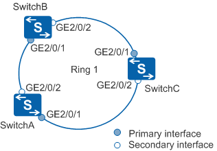
In Figure 1, SwitchA, SwitchB, and SwitchC constitute a ring network. The network is required to prevent loops when the ring is complete and to implement fast convergence to rapidly restore communication between nodes in the ring when the ring fails. You can enable RRPP on SwitchA, SwitchB, and SwitchC to meet this requirement.
Configuration Roadmap
The configuration roadmap is as follows:
Create an RRPP domain and its control VLAN.
Map VLANs from which data needs to pass through in the RRPP ring to instance 1, including data VLANs 100 to 300 and control VLANs 20 and 21 (VLAN 21 is the sub-control VLAN generated by the device).
Configure interfaces to be added to the RRPP domain on the devices so that data can pass through the interfaces. Disable protocols that conflict with RRPP, such as STP.
In the RRPP domain, configure a protected VLAN, create an RRPP ring and configure SwitchA, SwitchB, and SwitchC as nodes in ring 1 in domain 1. Configure SwitchA as the master node in ring 1 and configure SwitchB and SwitchC as transit nodes in ring 1.
Enable the RRPP ring and RRPP on devices.
Procedure
- Create an RRPP domain and its control VLAN.
# Configure SwitchA. The configurations of SwitchB and SwitchC are similar to the configuration of SwitchA, and are not mentioned here. For details, see the configuration files.
<HUAWEI> system-view
[HUAWEI] sysname SwitchA
[SwitchA] rrpp domain 1
[SwitchA-rrpp-domain-region1] control-vlan 20    //Each RRPP domain has a major control VLAN and a sub-control VLAN. You only need to specify the major control VLAN. The system uses the VLAN whose ID is one greater than the ID of the major control VLAN as the sub-control VLAN.
[SwitchA-rrpp-domain-region1] quit
- Map instance 1 to control VLANs 20 and 21 and data VLANs
100 to 300.
# Configure SwitchA. The configurations of SwitchB and SwitchC are similar to the configuration of SwitchA, and are not mentioned here. For details, see the configuration files.
[SwitchA] vlan batch 100 to 300
[SwitchA] stp region-configuration
[SwitchA-mst-region] instance 1 vlan 20 21 100 to 300  //Add the major control VLAN, sub-control VLAN, and data VLANs to instance 1.
[SwitchA-mst-region] active region-configuration
[SwitchA-mst-region] quit
- Configure the interfaces to be added to the RRPP ring as
trunk interfaces, configure the interfaces to allow VLANs 100 to 300
to pass through, and disable STP on the interfaces.
# Configure SwitchA. The configurations of SwitchB and SwitchC are similar to the configuration of SwitchA, and are not mentioned here. For details, see the configuration files.
[SwitchA] interface gigabitethernet 2/0/1
[SwitchA-GigabitEthernet2/0/1] port link-type trunk
[SwitchA-GigabitEthernet2/0/1] undo port trunk allow-pass vlan 1
[SwitchA-GigabitEthernet2/0/1] port trunk allow-pass vlan 100 to 300
[SwitchA-GigabitEthernet2/0/1] stp disable
[SwitchA-GigabitEthernet2/0/1] quit
[SwitchA] interface gigabitethernet 2/0/2
[SwitchA-GigabitEthernet2/0/2] port link-type trunk
[SwitchA-GigabitEthernet2/0/2] undo port trunk allow-pass vlan 1
[SwitchA-GigabitEthernet2/0/2] port trunk allow-pass vlan 100 to 300
[SwitchA-GigabitEthernet2/0/2] stp disable
[SwitchA-GigabitEthernet2/0/2] quit
- Specify a protected VLAN, and create and enable an RRPP
ring.
# Configure SwitchA.
[SwitchA] rrpp domain 1
[SwitchA-rrpp-domain-region1] protected-vlan reference-instance 1  //Configure instance 1 as the protected instance of the RRPP domain.
[SwitchA-rrpp-domain-region1] ring 1 node-mode master primary-port gigabitethernet 2/0/1 secondary-port gigabitethernet 2/0/2 level 0
[SwitchA-rrpp-domain-region1] ring 1 enable
[SwitchA-rrpp-domain-region1] quit
# Configure SwitchB.
[SwitchB] rrpp domain 1
[SwitchB-rrpp-domain-region1] protected-vlan reference-instance 1
[SwitchB-rrpp-domain-region1] ring 1 node-mode transit primary-port gigabitethernet 2/0/1 secondary-port gigabitethernet 2/0/2 level 0
[SwitchB-rrpp-domain-region1] ring 1 enable
[SwitchB-rrpp-domain-region1] quit
# Configure SwitchC.
[SwitchC] rrpp domain 1
[SwitchC-rrpp-domain-region1] protected-vlan reference-instance 1
[SwitchC-rrpp-domain-region1] ring 1 node-mode transit primary-port gigabitethernet 2/0/1 secondary-port gigabitethernet 2/0/2 level 0
[SwitchC-rrpp-domain-region1] ring 1 enable
[SwitchC-rrpp-domain-region1] quit
- Enable RRPP.
# Configure SwitchA. The configurations of SwitchB and SwitchC are similar to the configuration of SwitchA, and are not mentioned here. For details, see the configuration files.
[SwitchA] rrpp enable - Verify the configuration.
After the configuration is complete and the network topology becomes stable, perform the following operations to verify the configuration. The display on SwitchA is used as an example.
# Run the display rrpp brief command on SwitchA. The following information is displayed:
[SwitchA] display rrpp brief
Abbreviations for Switch Node Mode :
M - Master , T - Transit , E - Edge , A - Assistant-Edge

RRPP Protocol Status:  Enable
RRPP Working Mode: HW
RRPP Linkup Delay Timer: 0 sec (0 sec default)
Number of RRPP Domains: 1

Domain Index  : 1
Control VLAN  : major 20    sub 21
Protected VLAN : Reference Instance 1
Hello Timer   : 1 sec(default is 1 sec)  Fail Timer : 6 sec(default is 6 sec)

 Ring   Ring    Node     Primary/Common           Secondary/Edge          Is
 ID     Level   Mode     Port                     Port                    Enabled
 ----------------------------------------------------------------------------
 1      0       M        GigabitEthernet2/0/1     GigabitEthernet2/0/2    Yes
According to the preceding information, RRPP is enabled on SwitchA. The major control VLAN of RRPP domain 1 is VLAN 20 and the sub-control VLAN is VLAN 21. SwitchA is the master node in ring 1. The primary interface is GigabitEthernet2/0/1 and the secondary interface is GigabitEthernet2/0/2.
# Run the display rrpp verbose domain command on SwitchA. The following information is displayed:
[SwitchA] display rrpp verbose domain 1
Domain Index   : 1
Control VLAN   : major 20    sub 21
Protected VLAN : Reference Instance 1
Hello Timer    : 1 sec(default is 1 sec)  Fail Timer : 6 sec(default is 6 sec)

RRPP Ring      : 1
Ring Level     : 0
Node Mode      : Master
Ring State     : Complete
Is Enabled     : Enable                       Is Active: Yes
Primary port   : GigabitEthernet2/0/1         Port status: UP
Secondary port : GigabitEthernet2/0/2         Port status: BLOCKED
The command output shows that the RRPP ring is complete.
Configuration Files
SwitchA configuration file
#
sysname SwitchA
#
vlan batch 20 to 21 100 to 300
#
rrpp enable
#
stp region-configuration
 instance 1 vlan 20 to 21 100 to 300
 active region-configuration
#
rrpp domain 1
 control-vlan 20
 protected-vlan reference-instance 1
 ring 1 node-mode master primary-port GigabitEthernet2/0/1 secondary-port GigabitEthernet2/0/2 level 0
 ring 1 enable
#
interface GigabitEthernet2/0/1
 port link-type trunk
 undo port trunk allow-pass vlan 1
 port trunk allow-pass vlan 20 to 21 100 to 300
 stp disable
#
interface GigabitEthernet2/0/2
 port link-type trunk
 undo port trunk allow-pass vlan 1
 port trunk allow-pass vlan 20 to 21 100 to 300
 stp disable
#
return
SwitchB configuration file
#
sysname SwitchB
#
vlan batch 20 to 21 100 to 300
#
rrpp enable
#
stp region-configuration
 instance 1 vlan 20 to 21 100 to 300
 active region-configuration
#
rrpp domain 1
 control-vlan 20
 protected-vlan reference-instance 1
 ring 1 node-mode transit primary-port GigabitEthernet2/0/1 secondary-port GigabitEthernet2/0/2 level 0
 ring 1 enable
#
interface GigabitEthernet2/0/1
 port link-type trunk
 undo port trunk allow-pass vlan 1
 port trunk allow-pass vlan 20 to 21 100 to 300
 stp disable
#
interface GigabitEthernet2/0/2
 port link-type trunk
 undo port trunk allow-pass vlan 1
 port trunk allow-pass vlan 20 to 21 100 to 300
 stp disable
#
return
SwitchC configuration file
#
sysname SwitchC
#
vlan batch 20 to 21 100 to 300
#
rrpp enable
#
stp region-configuration
 instance 1 vlan 20 to 21 100 to 300
 active region-configuration
#
rrpp domain 1
 control-vlan 20
 protected-vlan reference-instance 1
 ring 1 node-mode transit primary-port GigabitEthernet2/0/1 secondary-port GigabitEthernet2/0/2 level 0
 ring 1 enable
#
interface GigabitEthernet2/0/1
 port link-type trunk
 undo port trunk allow-pass vlan 1
 port trunk allow-pass vlan 20 to 21 100 to 300
 stp disable
#
interface GigabitEthernet2/0/2
 port link-type trunk
 undo port trunk allow-pass vlan 1
 port trunk allow-pass vlan 20 to 21 100 to 300
 stp disable
#
return