Example for Configuring a VLL Using an MPLS TE Tunnel
Networking Requirements
The MPLS network of an ISP provides the L2VPN service to many users. The users connect to the MPLS network through PE1 and PE2, and users connected to the PE devices change frequently. A proper VPN solution is required to provide secure VPN services for users and to simplify the configuration when new users connect to the network.
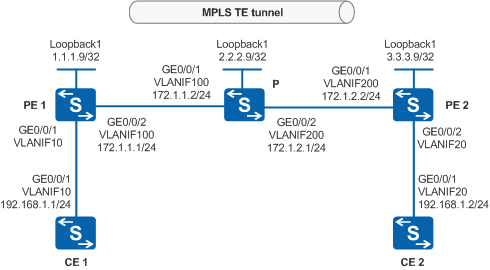
A VLL using an MPLS TE Tunnel, as shown in Figure 1, satisfies these requirements.

By default, LNP is enabled globally on the device. If a VLANIF interface is used as an AC-side interface for L2VPN, the configuration conflicts with LNP. In this case, run the lnp disable command in the system view to disable LNP.
The lnp disable command has no impact on services before the device restarts. After the device restarts, the device can only forward packets from the VLANs specified by the port default vlan command at Layer 2. The port default vlan 1 command is configured by default, so only packets of VLAN 1 can be forwarded at Layer 2.
Configuration Roadmap
MPLS TE tunnels can provide the FRR and hot standby functions to improve tunnel reliability.
A Martini VLL connection can be set up between CE1 and CE2, and a TE tunnel can be set up on the public network.
The configuration roadmap is as follows:
Add interfaces to VLANs, assign IP addresses to VLANIF interfaces, and configure an IGP on the PE and P devices of the backbone network to implement interworking between the devices.
Set up an MPLS TE tunnel and create a tunnel policy.
Set up a remote LDP session between the PE devices to exchange VC labels between them.
Create a VC connection between the PE devices, and apply a tunnel binding policy to the connection.
Procedure
- Add interfaces on the CE, PE, and P devices to VLANs, assign IP addresses to VLANIF interfaces, and configure an IGP on the PE and P devices of the backbone network according to Figure 1, to implement interworking between the devices.
# Configure CE1. The configuration of CE2 is similar to the configuration of CE1, and is not mentioned here.
<HUAWEI> system-view
[HUAWEI] sysname CE1
[CE1] vlan batch 10
[CE1] interface vlanif 10
[CE1-Vlanif10] ip address 192.168.1.1 255.255.255.0
[CE1-Vlanif10] quit
[CE1] interface gigabitethernet 0/0/1
[CE1-GigabitEthernet0/0/1] port link-type trunk
[CE1-GigabitEthernet0/0/1] port trunk allow-pass vlan 10
[CE1-GigabitEthernet0/0/1] quit
# Configure PE1. The configurations of PE2 and the P device are similar to the configuration of PE1, and are not mentioned here.
<HUAWEI> system-view
[HUAWEI] sysname PE1
[PE1] vlan batch 10 100
[PE1] interface vlanif 100
[PE1-Vlanif100] ip address 172.1.1.1 255.255.255.0
[PE1-Vlanif100] quit
[PE1] interface loopback 1
[PE1-LoopBack1] ip address 1.1.1.9 255.255.255.255
[PE1-LoopBack1] quit
[PE1] interface gigabitethernet 0/0/1
[PE1-GigabitEthernet0/0/1] port link-type trunk
[PE1-GigabitEthernet0/0/1] port trunk allow-pass vlan 10
[PE1-GigabitEthernet0/0/1] quit
[PE1] interface gigabitethernet 0/0/2
[PE1-GigabitEthernet0/0/2] port link-type trunk
[PE1-GigabitEthernet0/0/2] port trunk allow-pass vlan 100
[PE1-GigabitEthernet0/0/2] quit
[PE1] ospf 1
[PE1-ospf-1] area 0
[PE1-ospf-1-area-0.0.0.0] network 172.1.1.0 0.0.0.255
[PE1-ospf-1-area-0.0.0.0] network 1.1.1.9 0.0.0.0
[PE1-ospf-1-area-0.0.0.0] quit
[PE1-ospf-1] quit
- Set up an MPLS TE tunnel and create a tunnel binding policy.
Enable MPLS, MPLS TE, and RSVP-TE globally on PE1, P, and PE2, and on all interfaces along the tunnel. Enable constraint shortest path first (CSPF) on the ingress of the tunnel.
# Configure PE1.
[PE1] mpls lsr-id 1.1.1.9
[PE1] mpls
[PE1-mpls] mpls te
[PE1-mpls] mpls rsvp-te
[PE1-mpls] mpls te cspf
[PE1-mpls] quit
[PE1] interface vlanif 100
[PE1-Vlanif100] mpls
[PE1-Vlanif100] mpls te
[PE1-Vlanif100] mpls rsvp-te
[PE1-Vlanif100] quit
# Configure the P device.
[P] mpls lsr-id 2.2.2.9
[P] mpls
[P-mpls] mpls te
[P-mpls] mpls rsvp-te
[P-mpls] quit
[P] interface vlanif 100
[P-Vlanif100] mpls
[P-Vlanif100] mpls te
[P-Vlanif100] mpls rsvp-te
[P-Vlanif100] quit
[P] interface vlanif 200
[P-Vlanif200] mpls
[P-Vlanif200] mpls te
[P-Vlanif200] mpls rsvp-te
[P-Vlanif200] quit
# Configure PE2.
[PE2] mpls lsr-id 3.3.3.9
[PE2] mpls
[PE2-mpls] mpls te
[PE2-mpls] mpls rsvp-te
[PE2-mpls] mpls te cspf
[PE2-mpls] quit
[PE2] interface vlanif 200
[PE2-Vlanif200] mpls
[PE2-Vlanif200] mpls te
[PE2-Vlanif200] mpls rsvp-te
[PE2-Vlanif200] quit
Configure OSPF TE on the MPLS backbone network to advertise TE information.
# Configure PE1. The configurations of PE2 and the P device are similar to the configuration of PE1, and are not mentioned here.
[PE1] ospf 1
[PE1-ospf-1] opaque-capability enable
[PE1-ospf-1] area 0
[PE1-ospf-1-area-0.0.0.0] mpls-te enable
[PE1-ospf-1-area-0.0.0.0] quit
[PE1-ospf-1] quit
Configure tunnel interfaces for the MPLS TE tunnel and enable MPLS TE CSPF.
On the ingress of the tunnel, create a tunnel interface and set the IP address, tunnel protocol, destination IP address, tunnel ID, and dynamic signaling protocol for the tunnel interface. Then, run the mpls te commit command to commit the configuration.
# Configure PE1.
[PE1] interface tunnel 1
[PE1-Tunnel1] ip address unnumbered interface loopback 1
[PE1-Tunnel1] tunnel-protocol mpls te
[PE1-Tunnel1] destination 3.3.3.9
[PE1-Tunnel1] mpls te tunnel-id 100
[PE1-Tunnel1] mpls te signal-protocol rsvp-te
[PE1-Tunnel1] mpls te commit
[PE1-Tunnel1] quit
# Configure PE2.
[PE2] interface tunnel 1
[PE2-Tunnel1] ip address unnumbered interface loopback 1
[PE2-Tunnel1] tunnel-protocol mpls te
[PE2-Tunnel1] destination 1.1.1.9
[PE2-Tunnel1] mpls te tunnel-id 100
[PE2-Tunnel1] mpls te signal-protocol rsvp-te
[PE2-Tunnel1] mpls te commit
[PE2-Tunnel1] quit
After the configuration is complete, run the display mpls te tunnel-interface command on the PE devices at both ends of the tunnel. The command output shows that an MPLS TE tunnel is set up successfully. The command output of PE1 is used as an example.
[PE1]display mpls te tunnel-interface
    ----------------------------------------------------------------
                               Tunnel1
    ----------------------------------------------------------------
    Tunnel State Desc   :  UP
    Active LSP          :  Primary LSP
    Session ID          :  100
    Ingress LSR ID      :  1.1.1.9          Egress LSR ID:  3.3.3.9
    Admin State         :  UP               Oper State   :  UP
    Primary LSP State      : UP
      Main LSP State       : READY               LSP ID  : 1
Configure a tunnel binding policy.
# Configure PE1.
[PE1] interface tunnel 1
[PE1-Tunnel1] mpls te reserved-for-binding
[PE1-Tunnel1] mpls te commit
[PE1-Tunnel1] quit
[PE1] tunnel-policy 1
[PE1-tunnel-policy-1] tunnel binding destination 3.3.3.9 te tunnel 1
[PE1-tunnel-policy-1] quit
# Configure PE2.
[PE2] interface tunnel 1
[PE2-Tunnel1] mpls te reserved-for-binding
[PE2-Tunnel1] mpls te commit
[PE2-Tunnel1] quit
[PE2] tunnel-policy 1
[PE2-tunnel-policy-1] tunnel binding destination 1.1.1.9 te tunnel 1
[PE2-tunnel-policy-1] quit
- Create a remote LDP session between PE1 and PE2.
# Configure PE1.
[PE1] mpls ldp
[PE1-mpls-ldp] quit
[PE1] mpls ldp remote-peer 3.3.3.9
[PE1-mpls-ldp-remote-3.3.3.9] remote-ip 3.3.3.9
[PE1-mpls-ldp-remote-3.3.3.9] quit
# Configure PE2.
[PE2] mpls ldp
[PE2-mpls-ldp] quit
[PE2] mpls ldp remote-peer 1.1.1.9
[PE2-mpls-ldp-remote-1.1.1.9] remote-ip 1.1.1.9
[PE2-mpls-ldp-remote-1.1.1.9] quit
After the configuration is complete, run the display mpls ldp session command on PE1 to view the LDP session status. The command output shows that the LDP session status is Operational, indicating that a remote LDP session is established between PE1 and PE2.
The command output of PE1 is used as an example.
[PE1] display mpls ldp session

 LDP Session(s) in Public Network
 Codes: LAM(Label Advertisement Mode), SsnAge Unit(DDDD:HH:MM)
 A '*' before a session means the session is being deleted.
 ------------------------------------------------------------------------------
 PeerID             Status      LAM  SsnRole  SsnAge      KASent/Rcv
 ------------------------------------------------------------------------------
 3.3.3.9:0         Operational DU   Passive  0000:00:00  1/1
 ------------------------------------------------------------------------------
 TOTAL: 1 session(s) Found.
- Create a VC connection between the PE devices, and apply a tunnel binding policy to the connection.
# Configure PE1.In this example, a VLANIF interface is used as the AC-side interface, so you need to run the lnp disable command in the system view before performing the following steps. If you cannot disable LNP on the live network, do not use a VLANIF interface as the AC-side interface.
[PE1] mpls l2vpn
[PE1-l2vpn] quit
[PE1] interface vlanif 10
[PE1-Vlanif10] mpls l2vc 3.3.3.9 101 tunnel-policy 1
[PE1-Vlanif10] quit
# Configure PE2.In this example, a VLANIF interface is used as the AC-side interface, so you need to run the lnp disable command in the system view before performing the following steps. If you cannot disable LNP on the live network, do not use a VLANIF interface as the AC-side interface.
[PE2] mpls l2vpn
[PE2-l2vpn] quit
[PE2] interface vlanif 20
[PE2-Vlanif20] mpls l2vc 1.1.1.9 101 tunnel-policy 1
[PE2-Vlanif20] quit
- Verify the configuration.
Check the L2VPN connections on the PE devices. You can see that an L2VC is set up and is in Up state.
The command output of PE1 is used as an example.
[PE1] display mpls l2vc interface vlanif 10
 *client interface       : Vlanif10 is up
  Administrator PW       : no
  session state          : up
  AC status              : up
  Ignore AC state        : disable
  VC state               : up
  Label state            : 0
  Token state            : 0
  VC ID                  : 101
  VC type                : VLAN
  destination            : 3.3.3.9
  local group ID         : 0            remote group ID      : 0
  local VC label         : 1026         remote VC label      : 1032
  local AC OAM State     : up
  local PSN OAM State    : up
  local forwarding state : forwarding
  local status code      : 0x0
  remote AC OAM state    : up
  remote PSN OAM state   : up
  remote forwarding state: forwarding
  remote status code     : 0x0
  ignore standby state   : no
  BFD for PW             : unavailable
  VCCV State             : up
  manual fault           : not set
  active state           : active
  forwarding entry       : exist
  link state             : up
  local VC MTU           : 1500         remote VC MTU        : 1500
  local VCCV             : alert ttl lsp-ping bfd
  remote VCCV            : alert ttl lsp-ping bfd
  local control word     : disable      remote control word  : disable
  tunnel policy name     : 1
  PW template name       : --
  primary or secondary   : primary
  load balance type      : flow
  Access-port            : false
  Switchover Flag        : false
  VC tunnel/token info   : 1 tunnels/tokens
    NO.0  TNL type       : cr lsp, TNL ID : 0x48000002
    Backup TNL type      : lsp   , TNL ID : 0x0
  create time            : 0 days, 4 hours, 16 minutes, 25 seconds
  up time                : 0 days, 4 hours, 15 minutes, 58 seconds
  last change time       : 0 days, 4 hours, 15 minutes, 58 seconds
  VC last up time        : 2013/01/09 22:57:04
  VC total up time       : 0 days, 4 hours, 15 minutes, 58 seconds
  CKey                   : 4
  NKey                   : 3
  PW redundancy mode     : frr
  AdminPw interface      : --
  AdminPw link state     : --
  Diffserv Mode          : uniform
  Service Class          : be
  Color                  : --
  DomainId               : --
  Domain Name            : --
CE1 and CE2 can ping each other.
The command output of CE1 is used as an example.
[CE1] ping 192.168.1.2
  PING 192.168.1.2: 56  data bytes, press CTRL_C to break
    Reply from 192.168.1.2: bytes=56 Sequence=1 ttl=255 time=10 ms
    Reply from 192.168.1.2: bytes=56 Sequence=2 ttl=255 time=1 ms
    Reply from 192.168.1.2: bytes=56 Sequence=3 ttl=255 time=10 ms
    Reply from 192.168.1.2: bytes=56 Sequence=4 ttl=255 time=1 ms
    Reply from 192.168.1.2: bytes=56 Sequence=5 ttl=255 time=10 ms

  --- 192.168.1.2 ping statistics ---
    5 packet(s) transmitted
    5 packet(s) received
    0.00% packet loss
    round-trip min/avg/max = 1/6/10 ms
Configuration Files
CE1 configuration file
#
sysname CE1
#
vlan batch 10
#
interface Vlanif10
 ip address 192.168.1.1 255.255.255.0
#
interface GigabitEthernet0/0/1
 port link-type trunk
 port trunk allow-pass vlan 10
#
return
PE1 configuration file

The lnp disable command has no impact on services before the device restarts. After the device restarts, the device can only forward packets from the VLANs specified by the port default vlan command at Layer 2. The port default vlan 1 command is configured by default, so only packets of VLAN 1 can be forwarded at Layer 2.
#
sysname PE1
#
vlan batch 10 100
#
lnp disable #mpls lsr-id 1.1.1.9
mpls
 mpls te
 mpls rsvp-te
 mpls te cspf
#
mpls l2vpn
#
mpls ldp
#
mpls ldp remote-peer 3.3.3.9
 remote-ip 3.3.3.9
#
interface Vlanif10
 mpls l2vc 3.3.3.9 101 tunnel-policy 1
#
interface Vlanif100
 ip address 172.1.1.1 255.255.255.0
 mpls
 mpls te
 mpls rsvp-te
#
interface GigabitEthernet0/0/1
 port link-type trunk
 port trunk allow-pass vlan 10
#
interface GigabitEthernet0/0/2
 port link-type trunk
 port trunk allow-pass vlan 100
#
interface LoopBack1
 ip address 1.1.1.9 255.255.255.255
#
interface Tunnel1
 ip address unnumbered interface LoopBack1
 tunnel-protocol mpls te
 destination 3.3.3.9
 mpls te tunnel-id 100
 mpls te reserved-for-binding
 mpls te commit
#
ospf 1
 opaque-capability enable
 area 0.0.0.0
  network 1.1.1.9 0.0.0.0
  network 172.1.1.0 0.0.0.255
  mpls-te enable
#
tunnel-policy 1
 tunnel binding destination 3.3.3.9 te Tunnel1
#
return
P configuration file
#
sysname P
#
vlan batch 100 200
#
mpls lsr-id 2.2.2.9
mpls
 mpls te
 mpls rsvp-te
#
interface Vlanif100
 ip address 172.1.1.2 255.255.255.0
 mpls
 mpls te
 mpls rsvp-te
#
interface Vlanif200
 ip address 172.1.2.1 255.255.255.0
 mpls
 mpls te
 mpls rsvp-te
#
interface GigabitEthernet0/0/1
 port link-type trunk
 port trunk allow-pass vlan 100
#
interface GigabitEthernet0/0/2
 port link-type trunk
 port trunk allow-pass vlan 200
#
interface LoopBack1
 ip address 2.2.2.9 255.255.255.255
#
ospf 1
 opaque-capability enable
 area 0.0.0.0
  network 2.2.2.9 0.0.0.0
  network 172.1.1.0 0.0.0.255
  network 172.1.2.0 0.0.0.255
  mpls-te enable
#
return
PE2 configuration file
The lnp disable command has no impact on services before the device restarts. After the device restarts, the device can only forward packets from the VLANs specified by the port default vlan command at Layer 2. The port default vlan 1 command is configured by default, so only packets of VLAN 1 can be forwarded at Layer 2.
#
sysname PE2
#
vlan batch 20 200
#
lnp disable #mpls lsr-id 3.3.3.9
mpls
 mpls te
 mpls rsvp-te
 mpls te cspf
#
mpls l2vpn
#
mpls ldp
#
mpls ldp remote-peer 1.1.1.9
 remote-ip 1.1.1.9
#
interface Vlanif20
 mpls l2vc 1.1.1.9 101 tunnel-policy 1
#
interface Vlanif200
 ip address 172.1.2.2 255.255.255.0
 mpls
 mpls te
 mpls rsvp-te
#
interface GigabitEthernet0/0/1
 port link-type trunk
 port trunk allow-pass vlan 200
#
interface GigabitEthernet0/0/2
 port link-type trunk
 port trunk allow-pass vlan 20
#
interface LoopBack1
 ip address 3.3.3.9 255.255.255.255
#
interface Tunnel1
 ip address unnumbered interface LoopBack1
 tunnel-protocol mpls te
 destination 1.1.1.9
 mpls te tunnel-id 100
 mpls te reserved-for-binding
 mpls te commit
#
ospf 1
 opaque-capability enable
 area 0.0.0.0
  network 3.3.3.9 0.0.0.0
  network 172.1.2.0 0.0.0.255
  mpls-te enable
#
tunnel-policy 1
 tunnel binding destination 1.1.1.9 te Tunnel1
#
return
CE2 configuration file
#
sysname CE2
#
vlan batch 20
#
interface Vlanif20
 ip address 192.168.1.2 255.255.255.0
#
interface GigabitEthernet0/0/1
 port link-type trunk
 port trunk allow-pass vlan 20
#
return