Example for Configuring Interworking Between LDP VPLS and BGP AD VPLS in HVPLS Mode
Networking Requirements
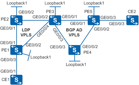
As shown in Figure 1, PE1 and PE2 support LDP VPLS, PE4 and PE5 support BGP AD VPLS, and PE3 supports both LDP VPLS and BGP AD VPLS. It is required that interworking between LDP VPLS and BGP AD VPLS be configured in HVPLS mode for CE1 and CE2 to communicate.
- Establish an LDP PW from PE1 to PE2 and from PE1 to PE3.
- Establish an LDP PW from PE2 to PE1 and from PE2 to PE3.
- Establish an LDP PW from PE3 to PE1 and from PE3 to PE2. Establish a BGP AD PW from PE3 to PE4 and from PE3 to PE5.
- Establish a BGP AD PW from PE4 to PE3 and from PE4 to PE5.
- Establish a BGP AD PW from PE5 to PE3 and from PE5 to PE4.

In this scenario, to avoid loops, ensure that all connected interfaces have STP disabled and connected interfaces are removed from VLAN 1. If STP is enabled and VLANIF interfaces of switches are used to construct a Layer 3 ring network, an interface on the network will be blocked. As a result, Layer 3 services on the network cannot run normally.
Switch |
Interface |
VLANIF Interface |
IP Address |
|---|---|---|---|
PE1 |
Loopback1 |
- |
1.1.1.9/32 |
PE1 |
GE0/0/1 |
VLANIF20 |
192.168.1.1/24 |
PE1 |
GE0/0/2 |
VLANIF40 |
192.168.2.1/24 |
PE1 |
GE0/0/3 |
VLANIF10 |
- |
PE2 |
Loopback1 |
- |
2.2.2.9/32 |
PE2 |
GE0/0/1 |
VLANIF20 |
192.168.1.2/24 |
PE2 |
GE0/0/2 |
VLANIF30 |
192.168.3.1/24 |
PE3 |
Loopback1 |
- |
3.3.3.9/32 |
PE3 |
GE0/0/1 |
VLANIF50 |
192.168.4.2/24 |
PE3 |
GE0/0/2 |
VLANIF30 |
192.168.3.2/24 |
PE3 |
GE0/0/3 |
VLANIF60 |
192.168.5.2/24 |
PE3 |
GE0/0/4 |
VLANIF40 |
192.168.2.2/24 |
PE4 |
Loopback1 |
- |
4.4.4.9/32 |
PE4 |
GE0/0/2 |
VLANIF70 |
192.168.6.2/24 |
PE4 |
GE0/0/3 |
VLANIF60 |
192.168.5.1/24 |
PE5 |
Loopback1 |
- |
5.5.5.9/32 |
PE5 |
GE0/0/1 |
VLANIF50 |
192.168.4.1/24 |
PE5 |
GE0/0/2 |
VLANIF70 |
192.168.6.1/24 |
PE5 |
GE0/0/3 |
VLANIF80 |
- |
CE1 |
GE0/0/1 |
VLANIF10 |
192.168.10.1/24 |
CE2 |
GE0/0/3 |
VLANIF80 |
192.168.10.2/24 |
Configuration Roadmap
The configuration roadmap is as follows:
- Configure an IP address and a routing protocol for each interface so that all PEs can communicate at the network layer.
Configure Multiprotocol Label Switching (MPLS) and public tunnels.
Configure PE1, PE2, and PE3 to form an LDP VPLS network.
When you configure LDP PWs from PE3 to PE1 and PE2, specify peers as user provider edges (UPEs).Configure PE3, PE4, and PE5 to form a BGP AD VPLS network.
Procedure
- Configure an IP address and a routing protocol for each
interface on the backbone network so that PEs can communicate at the
network layer.
This example uses OSPF as the routing protocol. For details about specific configurations, see the following configuration files.
After the configuration is complete, run the display ip routing-table command on PEs to verify that the PEs have learned each other's loopback interface IP address.
- Configure MPLS and public tunnels.
This example uses LDP LSPs as public tunnels. For details about specific configurations, see the following configuration files.
After the configuration is complete, run the display mpls ldp session command on PEs to verify that peer relationships have been established; run the display mpls lsp command to verify that LSPs have been established.
- Configure PE1, PE2, and PE3 to form an LDP VPLS network.
# Configure PE1.
[PE1] mpls l2vpn
[PE1-l2vpn] quit
[PE1] vsi vsi1 static
[PE1-vsi-vsi1] pwsignal ldp
[PE1-vsi-vsi1-ldp] vsi-id 1
[PE1-vsi-vsi1-ldp] peer 2.2.2.9
[PE1-vsi-vsi1-ldp] peer 3.3.3.9
[PE1-vsi-vsi1-ldp] quit
[PE1-vsi-vsi1] quit
# Configure PE2.
[PE2] mpls l2vpn
[PE2-l2vpn] quit
[PE2] vsi vsi1 static
[PE2-vsi-vsi1] pwsignal ldp
[PE2-vsi-vsi1-ldp] vsi-id 1
[PE2-vsi-vsi1-ldp] peer 1.1.1.9
[PE2-vsi-vsi1-ldp] peer 3.3.3.9
[PE2-vsi-vsi1-ldp] quit
[PE2-vsi-vsi1] quit
# Configure PE3.
[PE3] mpls l2vpn
[PE3-l2vpn] quit
[PE3] vsi vsi1
[PE3-vsi-vsi1] pwsignal ldp
[PE3-vsi-vsi1-ldp] vsi-id 1
[PE3-vsi-vsi1-ldp] peer 1.1.1.9 upe
[PE3-vsi-vsi1-ldp] peer 2.2.2.9 upe
[PE3-vsi-vsi1-ldp] quit
[PE3-vsi-vsi1] quit
# On PE1, bind the attachment circuit (AC) interface to the VSI.
[PE1] interface vlanif 10
[PE1-Vlanif10] l2 binding vsi vsi1
[PE1-Vlanif10] quit
- Configure PE3, PE4, and PE5 to form a BGP AD VPLS network.
- Create VSIs and configure the BGP AD signaling.
# Configure PE3.
[PE3] vsi vsi1
[PE3-vsi-vsi1] bgp-ad
[PE3-vsi-vsi1-bgpad] vpls-id 192.168.0.0:1
[PE3-vsi-vsi1-bgpad] vpn-target 100:1 import-extcommunity
[PE3-vsi-vsi1-bgpad] vpn-target 100:1 export-extcommunity
[PE3-vsi-vsi1-bgpad] quit
[PE3-vsi-vsi1] quit
On PE3, the LDP and BGP AD PWs must be configured in the same VSI.
# Configure PE4.
[PE4] mpls l2vpn
[PE4-l2vpn] quit
[PE4] vsi vsi1
[PE4-vsi-vsi1] bgp-ad
[PE4-vsi-vsi1-bgpad] vpls-id 192.168.0.0:1
[PE4-vsi-vsi1-bgpad] vpn-target 100:1 import-extcommunity
[PE4-vsi-vsi1-bgpad] vpn-target 100:1 export-extcommunity
[PE4-vsi-vsi1-bgpad] quit
[PE4-vsi-vsi1] quit
# Configure PE5.
[PE5] mpls l2vpn
[PE5-l2vpn] quit
[PE5] vsi vsi1
[PE5-vsi-vsi1] bgp-ad
[PE5-vsi-vsi1-bgpad] vpls-id 192.168.0.0:1
[PE5-vsi-vsi1-bgpad] vpn-target 100:1 import-extcommunity
[PE5-vsi-vsi1-bgpad] vpn-target 100:1 export-extcommunity
[PE5-vsi-vsi1-bgpad] quit
[PE5-vsi-vsi1] quit
- Create VSIs and configure the BGP AD signaling.
- Configure CEs.
# Configure CE1.
[CE1] interface gigabitethernet 0/0/1
[CE1-GigabitEthernet0/0/1] port link-type trunk
[CE1-GigabitEthernet0/0/1] port trunk allow-pass vlan 10
[CE1-GigabitEthernet0/0/1] quit
[CE1] interface vlanif 10
[CE1-Vlanif10] ip address 192.168.10.1 255.255.255.0
[CE1-Vlanif10] quit
# Configure CE2.
[CE2] interface gigabitethernet 0/0/3
[CE2-GigabitEthernet0/0/3] port link-type trunk
[CE2-GigabitEthernet0/0/3] port trunk allow-pass vlan 80
[CE2-GigabitEthernet0/0/3] quit
[CE2] interface vlanif 80
[CE2-Vlanif80] ip address 192.168.10.2 255.255.255.0
[CE2-Vlanif80] quit
- Verify the configuration, Ping CE2 from CE1. The command
output shows that the ping is successful.
[CE1] ping 192.168.10.2
  PING 192.168.10.2: 56  data bytes, press CTRL_C to break
    Reply from 192.168.10.2: bytes=56 Sequence=1 ttl=255 time=190 ms
    Reply from 192.168.10.2: bytes=56 Sequence=2 ttl=255 time=190 ms
    Reply from 192.168.10.2: bytes=56 Sequence=3 ttl=255 time=140 ms
    Reply from 192.168.10.2: bytes=56 Sequence=4 ttl=255 time=140 ms
    Reply from 192.168.10.2: bytes=56 Sequence=5 ttl=255 time=110 ms

  --- 192.168.10.2 ping statistics ---
    5 packet(s) transmitted
    5 packet(s) received
    0.00% packet loss
    round-trip min/avg/max = 110/154/190 ms
Configuration Files
PE1 configuration file
#
sysname PE1
#
vlan batch 10 20 40
#
mpls lsr-id 1.1.1.9
mpls
#
mpls l2vpn
#
vsi vsi1 static
 pwsignal ldp
  vsi-id 1
  peer 2.2.2.9
  peer 3.3.3.9
#
mpls ldp
#
interface Vlanif10
 l2 binding vsi vsi1
#
interface Vlanif20
 ip address 192.168.1.1 255.255.255.0
 mpls
 mpls ldp
#
interface Vlanif40
 ip address 192.168.2.1 255.255.255.0
 mpls
 mpls ldp
#
interface GigabitEthernet0/0/1
 port link-type trunk
 port trunk allow-pass vlan 20
#
interface GigabitEthernet0/0/2
 port link-type trunk
 port trunk allow-pass vlan 40
#
interface GigabitEthernet0/0/3
 port link-type trunk
 port trunk allow-pass vlan 10
#
interface LoopBack1
 ip address 1.1.1.9 255.255.255.255
#
ospf 1
 area 0.0.0.0
  network 1.1.1.9 0.0.0.0
  network 192.168.1.0 0.0.0.255
  network 192.168.2.0 0.0.0.255
#
return
PE2 configuration file
#
sysname PE2
#
vlan batch 20 30
#
mpls lsr-id 2.2.2.9
mpls
#
mpls l2vpn
#
vsi vsi1 static
 pwsignal ldp
  vsi-id 1
  peer 1.1.1.9
  peer 3.3.3.9
#
mpls ldp
#
interface Vlanif20
 ip address 192.168.1.2 255.255.255.0
 mpls
 mpls ldp
#
interface Vlanif30
 ip address 192.168.3.1 255.255.255.0
 mpls
 mpls ldp
#
interface GigabitEthernet0/0/1
 port link-type trunk
 port trunk allow-pass vlan 20
#
interface GigabitEthernet0/0/2
 port link-type trunk
 port trunk allow-pass vlan 30
#
interface LoopBack1
 ip address 2.2.2.9 255.255.255.255
#
ospf 1
 area 0.0.0.0
  network 2.2.2.9 0.0.0.0
  network 192.168.1.0 0.0.0.255
  network 192.168.3.0 0.0.0.255
#
return
PE3 configuration file
#
sysname PE3
#
vlan batch 30 40 50 60
#
mpls lsr-id 3.3.3.9
mpls
#
mpls l2vpn
#
vsi vsi1
 pwsignal ldp
  vsi-id 1
  peer 1.1.1.9 upe
  peer 2.2.2.9 upe
 bgp-ad
  vpls-id 192.168.0.0:1
  vpn-target 100:1 import-extcommunity
  vpn-target 100:1 export-extcommunity
#
mpls ldp
#
interface Vlanif30
 ip address 192.168.3.2 255.255.255.0
 mpls
 mpls ldp
#
interface Vlanif40
 ip address 192.168.2.2 255.255.255.0
 mpls
 mpls ldp
#
interface Vlanif50
 ip address 192.168.4.2 255.255.255.0
 mpls
 mpls ldp
#
interface Vlanif60
 ip address 192.168.5.2 255.255.255.0
 mpls
 mpls ldp
#
interface GigabitEthernet0/0/1
 port link-type trunk
 port trunk allow-pass vlan 50
#
interface GigabitEthernet0/0/2
 port link-type trunk
 port trunk allow-pass vlan 30
#
interface GigabitEthernet0/0/3
 port link-type trunk
 port trunk allow-pass vlan 60
#
interface GigabitEthernet0/0/4
 port link-type trunk
 port trunk allow-pass vlan 40
#
interface LoopBack1
 ip address 3.3.3.9 255.255.255.255
#
bgp 100
 peer 4.4.4.9 as-number 100
 peer 4.4.4.9 connect-interface LoopBack1
 peer 5.5.5.9 as-number 100
 peer 5.5.5.9 connect-interface LoopBack1
 #
 ipv4-family unicast
  undo synchronization
  peer 4.4.4.9 enable
  peer 5.5.5.9 enable
 #
 l2vpn-ad-family
  policy vpn-target
  peer 4.4.4.9 enable
  peer 5.5.5.9 enable
#
ospf 1
 area 0.0.0.0
  network 3.3.3.9 0.0.0.0
  network 192.168.2.0 0.0.0.255
  network 192.168.3.0 0.0.0.255
  network 192.168.4.0 0.0.0.255
  network 192.168.5.0 0.0.0.255
#
return
PE4 configuration file
#
sysname PE4
#
vlan batch 60 70
#
mpls lsr-id 4.4.4.9
mpls
#
mpls l2vpn
#
vsi vsi1
 bgp-ad
  vpls-id 192.168.0.0:1
  vpn-target 100:1 import-extcommunity
  vpn-target 100:1 export-extcommunity
#
mpls ldp
#
interface Vlanif60
 ip address 192.168.5.1 255.255.255.0
 mpls
 mpls ldp
#
interface Vlanif70
 ip address 192.168.6.2 255.255.255.0
 mpls
 mpls ldp
#
interface GigabitEthernet0/0/2
 port link-type trunk
 port trunk allow-pass vlan 70
#
interface GigabitEthernet0/0/3
 port link-type trunk
 port trunk allow-pass vlan 60
#
interface LoopBack1
 ip address 4.4.4.9 255.255.255.255
#
bgp 100
 peer 3.3.3.9 as-number 100
 peer 3.3.3.9 connect-interface LoopBack1
 peer 5.5.5.9 as-number 100
 peer 5.5.5.9 connect-interface LoopBack1
 #
 ipv4-family unicast
  undo synchronization
  peer 3.3.3.9 enable
  peer 5.5.5.9 enable
 #
 l2vpn-ad-family
  policy vpn-target
  peer 3.3.3.9 enable
  peer 5.5.5.9 enable
#
ospf 1
 area 0.0.0.0
  network 4.4.4.9 0.0.0.0
  network 192.168.5.0 0.0.0.255
  network 192.168.6.0 0.0.0.255
#
return
PE5 configuration file
#
sysname PE5
#
vlan batch 50 70 80
#
mpls lsr-id 5.5.5.9
mpls
#
mpls l2vpn
#
vsi vsi1
 bgp-ad
  vpls-id 192.168.0.0:1
  vpn-target 100:1 import-extcommunity
  vpn-target 100:1 export-extcommunity
#
mpls ldp
#
interface Vlanif50
 ip address 192.168.4.1 255.255.255.0
 mpls
 mpls ldp
#
interface Vlanif70
 ip address 192.168.6.1 255.255.255.0
 mpls
 mpls ldp
#
interface Vlanif80
 l2 binding vsi vsi1
#
interface GigabitEthernet0/0/1
 port link-type trunk
 port trunk allow-pass vlan 50
#
interface GigabitEthernet0/0/2
 port link-type trunk
 port trunk allow-pass vlan 70
#
interface GigabitEthernet0/0/3
 port link-type trunk
 port trunk allow-pass vlan 80
#
interface LoopBack1
 ip address 5.5.5.9 255.255.255.255
#
bgp 100
 peer 3.3.3.9 as-number 100
 peer 3.3.3.9 connect-interface LoopBack1
 peer 4.4.4.9 as-number 100
 peer 4.4.4.9 connect-interface LoopBack1
 #
 ipv4-family unicast
  undo synchronization
  peer 3.3.3.9 enable
  peer 4.4.4.9 enable
 #
 l2vpn-ad-family
  policy vpn-target
  peer 3.3.3.9 enable
  peer 4.4.4.9 enable
#
ospf 1
 area 0.0.0.0
  network 5.5.5.9 0.0.0.0
  network 192.168.4.0 0.0.0.255
  network 192.168.6.0 0.0.0.255
#
return
CE1 configuration file
#
sysname CE1
#
vlan batch 10
#
interface Vlanif10
 ip address 192.168.10.1 255.255.255.0
#
interface GigabitEthernet0/0/1
 port link-type trunk
 port trunk allow-pass vlan 10
#
return
CE2 configuration file
#
sysname CE2
#
vlan batch 80
#
interface Vlanif80
 ip address 192.168.10.2 255.255.255.0
#
interface GigabitEthernet0/0/3
 port link-type trunk
 port trunk allow-pass vlan 80
#
return