Example for Configuring Static VLLs to Access a VPLS Network
Networking Requirements
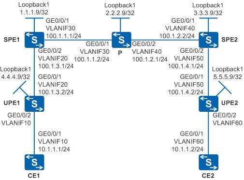
Figure 1 shows a backbone network built by an enterprise. UPEs do not support dynamic VLLs, and access SPEs through static VLLs. Site1 connects to UPE1 through CE1 and then connects to the backbone network. Site2 connects to UPE2 through CE2 and then connects to the backbone network. Users at Site1 and Site2 need to communicate at Layer 2 and user information needs to be reserved when Layer 2 packets are transmitted over the backbone network.
Configuration Roadmap
The configuration roadmap is as follows:
Configure transparent transmission of Layer 2 packets over the backbone network using VPLS to enable users at Site1 and Site2 to communicate at Layer 2 and reserve user information when Layer 2 packets are transmitted over the backbone network.
Use Martini VPLS to implement Layer 2 communication between CEs based on enterprise network planning requirements.
Configure the IGP routing protocol on the UPEs, SPEs, and P to implement data transmission on the public network between PEs.
Configure MPLS and LDP on the SPEs and P to support VPLS.
Establish tunnels for transmitting data between PEs to prevent data from being known by the public network, including dynamic LSPs between SPEs and static LSPs between UPEs and SPEs.
Enable MPLS L2VPN on PEs to implement VPLS.
Establish VLLs between UPEs and SPEs in SVC mode, configure static VLLs and VSIs on SPEs, enable MAC-withdraw on VSIs, and configure static VLLs on UPEs for accessing SPEs.
Create VSIs on SPEs, specify LDP as the signaling protocol, and bind the VSIs to AC interfaces to implement Martini VPLS.
Procedure
- Configure VLANs that interfaces belong to.
Configure the VLAN that each interface belongs to and assign IP addresses to interfaces on Switch.
# Configure CE1. The configuration on UPE1, UPE2, SPE1, SPE2, P, and CE2 is similar to the CE1, and is not mentioned here.
<HUAWEI> system-view
[HUAWEI] sysname CE1
[CE1] vlan 10
[CE1-vlan10] quit
[CE1] interface vlanif 10
[CE1-Vlanif10] ip address 10.1.1.1 255.255.255.0
[CE1-Vlanif10] quit
[CE1] interface gigabitethernet 0/0/1
[CE1-GigabitEthernet0/0/1] port link-type trunk
[CE1-GigabitEthernet0/0/1] port trunk allow-pass vlan 10
[CE1-GigabitEthernet0/0/1] quit

Do not add AC-side physical interfaces and PW-side physical interfaces of a PE to the same VLAN; otherwise, a loop may occur.
- Configure the IGP protocol. OSPF is used in this example.
Configure the IP address of the loopback interface on UPE1, UPE2, SPE1, SPE2, and P.
# Configure SPE1. The configuration on UPE1, UPE2, SPE2, and P is similar to the SPE1, and is not mentioned here.
[SPE1] interface loopback 1
[SPE1-LoopBack1] ip address 1.1.1.9 255.255.255.255
[SPE1-LoopBack1] quit
Configure OSPF on SPEs and P to advertise the network segment and the host routes of LSR IDs.
# Configure SPE1.
[SPE1] ospf
[SPE1-ospf-1] area 0
[SPE1-ospf-1-area-0.0.0.0] network 1.1.1.9 0.0.0.0
[SPE1-ospf-1-area-0.0.0.0] network 100.1.1.0 0.0.0.255
[SPE1-ospf-1-area-0.0.0.0] network 100.1.3.0 0.0.0.255
[SPE1-ospf-1-area-0.0.0.0] quit
[SPE1-ospf-1] quit
# Configure the P.
[P] ospf
[P-ospf-1] area 0
[P-ospf-1-area-0.0.0.0] network 2.2.2.9 0.0.0.0
[P-ospf-1-area-0.0.0.0] network 100.1.1.0 0.0.0.255
[P-ospf-1-area-0.0.0.0] network 100.1.2.0 0.0.0.255
[P-ospf-1-area-0.0.0.0] quit
[P-ospf-1] quit
# Configure SPE2.
[SPE2] ospf
[SPE2-ospf-1] area 0
[SPE2-ospf-1-area-0.0.0.0] network 3.3.3.9 0.0.0.0
[SPE2-ospf-1-area-0.0.0.0] network 100.1.2.0 0.0.0.255
[SPE2-ospf-1-area-0.0.0.0] network 100.1.4.0 0.0.0.255
[SPE2-ospf-1-area-0.0.0.0] quit
[SPE2-ospf-1] quit
# Configure UPE1.
[UPE1] ospf
[UPE1-ospf-1] area 0
[UPE1-ospf-1-area-0.0.0.0] network 4.4.4.9 0.0.0.0
[UPE1-ospf-1-area-0.0.0.0] network 100.1.3.0 0.0.0.255
[UPE1-ospf-1-area-0.0.0.0] quit
[UPE1-ospf-1] quit
# Configure UPE2.
[UPE2] ospf
[UPE2-ospf-1] area 0
[UPE2-ospf-1-area-0.0.0.0] network 5.5.5.9 0.0.0.0
[UPE2-ospf-1-area-0.0.0.0] network 100.1.4.0 0.0.0.255
[UPE2-ospf-1-area-0.0.0.0] quit
[UPE2-ospf-1] quit
After the configuration is complete, run the display ip routing-table command on PE1, P, and PE2. You can view the routes learned by PE1, P, and PE2 from each other.
- Configure basic MPLS functions and LDP.
Configure basic MPLS functions and LDP on SPE1, P, and SPE2.
# Configure SPE1.
[SPE1] mpls lsr-id 1.1.1.9
[SPE1] mpls
[SPE1-mpls] quit
[SPE1] mpls ldp
[SPE1-mpls-ldp] quit
[SPE1] interface vlanif 30
[SPE1-Vlanif30] mpls
[SPE1-Vlanif30] mpls ldp
[SPE1-Vlanif30] quit
[SPE1] interface vlanif 20
[SPE1-Vlanif20] mpls
[SPE1-Vlanif20] quit
# Configure the P.
[P] mpls lsr-id 2.2.2.9
[P] mpls
[P-mpls] quit
[P] mpls ldp
[P-mpls-ldp] quit
[P] interface vlanif 30
[P-Vlanif30] mpls
[P-Vlanif30] mpls ldp
[P-Vlanif30] quit
[P] interface vlanif 40
[P-Vlanif40] mpls
[P-Vlanif40] mpls ldp
[P-Vlanif40] quit
# Configure SPE2.
[SPE2] mpls lsr-id 3.3.3.9
[SPE2] mpls
[SPE2-mpls] quit
[SPE2] mpls ldp
[SPE2-mpls-ldp] quit
[SPE2] interface vlanif 40
[SPE2-Vlanif40] mpls
[SPE2-Vlanif40] mpls ldp
[SPE2-Vlanif40] quit
[SPE2] interface vlanif 50
[SPE2-Vlanif50] mpls
[SPE2-Vlanif50] quit
After the configuration is complete, run the display mpls ldp session command on SPE1, P, and SPE2. You can see that the status of the peer relationship between SPE1 and P or between SPE2 and P is Operational, which indicates that the peer relationship is established. Run the display mpls lsp command to view the LSP status.
The information displayed on SPE1 is used as an example.
[SPE1] display mpls ldp session

 LDP Session(s) in Public Network
 Codes: LAM(Label Advertisement Mode), SsnAge Unit(DDDD:HH:MM)
 A '*' before a session means the session is being deleted.
 ------------------------------------------------------------------------------
 PeerID             Status      LAM  SsnRole  SsnAge      KASent/Rcv
 ------------------------------------------------------------------------------
 2.2.2.9:0          Operational DU   Passive  0000:00:00  2/2
 ------------------------------------------------------------------------------
 TOTAL: 1 session(s) Found.
[SPE1] display mpls lsp Flag after Out IF: (I) - LSP Is Only Iterated by RLFA ------------------------------------------------------------------------------- LSP Information: LDP LSP ------------------------------------------------------------------------------- FEC In/Out Label In/Out IF Vrf Name 1.1.1.9/32 3/NULL -/- 2.2.2.9/32 NULL/3 -/Vlanif30 2.2.2.9/32 4096/3 -/Vlanif30 3.3.3.9/32 NULL/4097 -/Vlanif30 3.3.3.9/32 4097/4097 -/Vlanif30 - Set up remote LDP sessions between SPEs.
# Configure SPE1.
[SPE1] mpls ldp remote-peer 3.3.3.9
[SPE1-mpls-ldp-remote-3.3.3.9] remote-ip 3.3.3.9
[SPE1-mpls-ldp-remote-3.3.3.9] quit
# Configure SPE2.
[SPE2] mpls ldp remote-peer 1.1.1.9
[SPE2-mpls-ldp-remote-1.1.1.9] remote-ip 1.1.1.9
[SPE2-mpls-ldp-remote-1.1.1.9] quit
After the configuration is complete, run the display mpls ldp session command on SPE1 and SPE2. You can see that the status of the peer relationship between SPE1 and SPE2 is Operational, which indicates that the peer relationship is established.
The information displayed on SPE1 is used as an example.
[SPE1] display mpls ldp session

 LDP Session(s) in Public Network
 Codes: LAM(Label Advertisement Mode), SsnAge Unit(DDDD:HH:MM)
 A '*' before a session means the session is being deleted.
 ------------------------------------------------------------------------------
 PeerID             Status      LAM  SsnRole  SsnAge      KASent/Rcv
 ------------------------------------------------------------------------------
 2.2.2.9:0          Operational DU   Passive  0000:00:02  10/10
 3.3.3.9:0          Operational DU   Passive  0000:00:01  5/5
 ------------------------------------------------------------------------------
 TOTAL: 2 session(s) Found.
- Establish static LSPs between UPEs and SPEs.
# Configure UPE1.
[UPE1] mpls lsr-id 4.4.4.9
[UPE1] mpls
[UPE1-mpls] quit
[UPE1] interface vlanif 20
[UPE1-Vlanif20] mpls
[UPE1-Vlanif20] quit
[UPE1] static-lsp ingress UPE1toSPE1 destination 1.1.1.9 32 nexthop 100.1.3.1 out-label 20
[UPE1] static-lsp egress SPE1toUPE1 incoming-interface vlanif 20 in-label 30
# Configure UPE2.
[UPE2] mpls lsr-id 5.5.5.9
[UPE2] mpls
[UPE2-mpls] quit
[UPE2] interface vlanif 50
[UPE2-Vlanif50] mpls
[UPE2-Vlanif50] quit
[UPE2] static-lsp ingress UPE2toSPE2 destination 3.3.3.9 32 nexthop 100.1.4.1 out-label 40
[UPE2] static-lsp egress SPE2toUPE2 incoming-interface vlanif 50 in-label 50
# Configure SPE1.
[SPE1] static-lsp ingress SPE1toUPE1 destination 4.4.4.9 32 nexthop 100.1.3.2 out-label 30
[SPE1] static-lsp egress UPE1toSPE1 incoming-interface vlanif 20 in-label 20
# Configure SPE2.
[SPE2] static-lsp ingress SPE2toUPE2 destination 5.5.5.9 32 nexthop 100.1.4.2 out-label 50
[SPE2] static-lsp egress UPE2toSPE2 incoming-interface vlanif 50 in-label 40
- Enable MPLS L2VPN on UPEs and configure the UPEs to access SPEs through static VLLs.
# Configure UPE1.
[UPE1] mpls l2vpn
[UPE1-l2vpn] quit
[UPE1] interface vlanif 10
[UPE1-Vlanif10] mpls static-l2vc destination 1.1.1.9 transmit-vpn-label 100 receive-vpn-label 100
[UPE1-Vlanif10] quit
# Configure UPE2.
[UPE2] mpls l2vpn
[UPE2-l2vpn] quit
[UPE2] interface vlanif 60
[UPE2-Vlanif60] mpls static-l2vc destination 3.3.3.9 transmit-vpn-label 100 receive-vpn-label 100
[UPE2-Vlanif60] quit
- Enable MPLS L2VPN and configure VSIs on SPEs.
# Configure SPE1.
[SPE1] mpls l2vpn
[SPE1-l2vpn] quit
[SPE1] vsi V100 static
[SPE1-vsi-V100] pwsignal ldp
[SPE1-vsi-V100-ldp] vsi-id 100
[SPE1-vsi-V100-ldp] mac-withdraw enable
[SPE1-vsi-V100-ldp] peer 3.3.3.9
[SPE1-vsi-V100-ldp] peer 4.4.4.9 static-upe trans 100 recv 100
[SPE1-vsi-V100-ldp] quit
[SPE1-vsi-V100] quit
# Configure SPE2.
[SPE2] mpls l2vpn
[SPE2-l2vpn] quit
[SPE2] vsi V100 static
[SPE2-vsi-V100] pwsignal ldp
[SPE2-vsi-V100-ldp] vsi-id 100
[SPE2-vsi-V100-ldp] mac-withdraw enable
[SPE2-vsi-V100-ldp] peer 1.1.1.9
[SPE2-vsi-V100-ldp] peer 5.5.5.9 static-upe trans 100 recv 100
[SPE2-vsi-V100-ldp] quit
[SPE2-vsi-V100] quit
- Verify the configuration.
After the configurations are complete, run the display mpls static-l2vc on UPEs. You can see that static VLLs are established and the VC status is Up. The information displayed on UPE1 is used as an example.
[UPE1] display mpls static-l2vc interface vlanif 10
 *Client Interface     : Vlanif10 is up
  AC Status            : up
  Ignore AC state      : disable
  VC State             : up
  VC ID                : 0
  VC Type              : VLAN
  Destination          : 1.1.1.9
  Transmit VC Label    : 100
  Receive VC Label     : 100
  Label Status         : 0
  Token Status         : 0
  Control Word         : Disable
  VCCV Capability      : alert ttl lsp-ping bfd
  active state         : active
  Link State           : up
  Tunnel Policy        : --
  PW Template Name     : --
  Main or Secondary    : Main
  load balance type    : flow
  Access-port          : false
  VC tunnel/token info : 1 tunnels/tokens
  NO.0  TNL Type       : lsp   , TNL ID : 0x2
  Backup TNL Type      : lsp   , TNL ID : 0x0
  Create time          : 0 days, 0 hours, 1 minutes, 4 seconds
  UP time              : 0 days, 0 hours, 1 minutes, 4 seconds
  Last change time     : 0 days, 0 hours, 1 minutes, 4 seconds
  VC last up time      : 2014/11/13 14:07:19
  VC total up time     : 0 days, 0 hours, 1 minutes, 4 seconds
  CKey                 : 4
  NKey                 : 3
  Diffserv Mode        : uniform
  Service Class        : be
  Color                : --
  DomainId             : --
  Domain Name          : --
  BFD for PW           : unavailable
Run the display vsi name V100 command on SPEs, and you can see that the VSI named v100 is in Up state and the PW is also in Up state. The information displayed on SPE1 is used as an example.
[SPE1] display vsi name V100 verbose

 ***VSI Name               : V100
    Administrator VSI      : no
    Isolate Spoken         : disable
    VSI Index              : 0
    PW Signaling           : ldp
    Member Discovery Style : static
    PW MAC Learn Style     : unqualify
    Encapsulation Type     : vlan
    MTU                    : 1500
    Diffserv Mode          : uniform
    Mpls Exp               : --
    DomainId               : 255
    Domain Name            :
    Ignore AcState         : disable
    P2P VSI                : disable
    Create Time            : 0 days, 0 hours, 2 minutes, 5 seconds
    VSI State              : up

    VSI ID                 : 100
    LDP MAC-WITHDRAW       : mac-withdraw Enable
   *Peer Router ID         : 3.3.3.9
    Negotiation-vc-id      : 100
    primary or secondary   : primary
    ignore-standby-state   : no
    VC Label               : 4098
    Peer Type              : dynamic
    Session                : up
    Tunnel ID              : 0x8c
    Broadcast Tunnel ID    : 0x8c
    Broad BackupTunnel ID  : 0x0
    CKey                   : 13
    NKey                   : 14
    Stp Enable             : 0
    PwIndex                : 0
    Control Word           : disable
   *Peer Router ID         : 4.4.4.9
    Negotiation-vc-id      : 100
    primary or secondary   : primary
    ignore-standby-state   : no
    VC Label               : 100
    Peer Type              : static
    Tunnel ID              : 0x8e
    Broadcast Tunnel ID    : 0x8e
    Broad BackupTunnel ID  : 0x0
    CKey                   : 19
    NKey                   : 20
    Stp Enable             : 0
    PwIndex                : 0
    Control Word           : disable

  **PW Information:

   *Peer Ip Address        : 4.4.4.9
    PW State               : up
    Local VC Label         : 100
    Remote VC Label        : 100
    Remote Control Word    : disable
    PW Type                : MEHVPLS
    Local  VCCV            : alert lsp-ping bfd
    Remote VCCV            : alert lsp-ping bfd
    Tunnel ID              : 0x8e
    Broadcast Tunnel ID    : 0x8e
    Broad BackupTunnel ID  : 0x0
    Ckey                   : 0x13
    Nkey                   : 0x14
    Main PW Token          : 0x8e
    Slave PW Token         : 0x0
    Tnl Type               : LSP
    OutInterface           : Vlanif20
    Backup OutInterface    :
    Stp Enable             : 0
    PW Last Up Time        : 2014/11/13 14:06:25
    PW Total Up Time       : 0 days, 0 hours, 2 minutes, 5 seconds
   *Peer Ip Address        : 3.3.3.9
    PW State               : up
    Local VC Label         : 4098
    Remote VC Label        : 4098
    Remote Control Word    : disable
    PW Type                : label
    Local  VCCV            : alert lsp-ping bfd
    Remote VCCV            : alert lsp-ping bfd
    Tunnel ID              : 0x8c
    Broadcast Tunnel ID    : 0x8c
    Broad BackupTunnel ID  : 0x0
    Ckey                   : 0xd
    Nkey                   : 0xe
    Main PW Token          : 0x8c
    Slave PW Token         : 0x0
    Tnl Type               : LSP
    OutInterface           : Vlanif30
    Backup OutInterface    :
    Stp Enable             : 0
    PW Last Up Time        : 2014/11/13 14:06:26
    PW Total Up Time       : 0 days, 0 hours, 2 minutes, 4 seconds
CE1 and CE2, which reside in the same network segment, can ping each other.
[CE1] ping 10.1.1.2
  PING 10.1.1.2: 56  data bytes, press CTRL_C to break
    Reply from 10.1.1.2: bytes=56 Sequence=1 ttl=255 time=90 ms
    Reply from 10.1.1.2: bytes=56 Sequence=2 ttl=255 time=77 ms
    Reply from 10.1.1.2: bytes=56 Sequence=3 ttl=255 time=34 ms
    Reply from 10.1.1.2: bytes=56 Sequence=4 ttl=255 time=46 ms
    Reply from 10.1.1.2: bytes=56 Sequence=5 ttl=255 time=94 ms

  --- 10.1.1.2 ping statistics ---
    5 packet(s) transmitted
    5 packet(s) received
    0.00% packet loss
    round-trip min/avg/max = 34/68/94 ms
After you run the shutdown command on VLANIF 10 (to which the VSI is bound) of UPE1, CE1 and CE2 cannot ping each other successfully. This indicates that data is transmitted through the PW of this VSI.
Before GigabitEthernet0/0/2 of SPE1 is shut down, view the MAC address table learned by the VSI on the SPE2 (only the dynamic MAC address of the VSI named V100 is provided here).
[SPE2] display mac-address vsi V100
-------------------------------------------------------------------------------
MAC Address    VLAN/VSI/BD                          Learned-From        Type
-------------------------------------------------------------------------------
0044-0141-5411 -/V100/-                            GE0/0/1            dynamic
4c1f-cc64-a1a0 -/V100/-                            GE0/0/2            dynamic

-------------------------------------------------------------------------------
Total items displayed = 2
After GigabitEthernet0/0/2 of SPE1 is shut down, set the status of the VSI bound to the static VLL to Down. View the MAC address table learned by the VSI on SPE2, and you can see that the MAC address learned from GigabitEthernet0/0/2 has been deleted.
[SPE1] interface gigabitethernet 0/0/2
[SPE1-GigabitEthernet0/0/2] shutdown
[SPE1-GigabitEthernet0/0/2] quit
[SPE2] display mac-address vsi V100
-------------------------------------------------------------------------------
MAC Address    VLAN/VSI/BD                          Learned-From        Type
-------------------------------------------------------------------------------

-------------------------------------------------------------------------------
Total items displayed = 0
Configuration Files
CE1 configuration file
#
sysname CE1
#
vlan batch 10
#
interface Vlanif10
 ip address 10.1.1.1 255.255.255.0
#
interface GigabitEthernet0/0/1
 port link-type trunk
 port trunk allow-pass vlan 10
#
return
CE2 configuration file
#
sysname CE2
#
vlan batch 60
#
interface Vlanif60
 ip address 10.1.1.2 255.255.255.0
#
interface GigabitEthernet0/0/1
 port link-type trunk
 port trunk allow-pass vlan 60
#
return
UPE1 configuration file
#
sysname UPE1
#
vlan batch 10 20
#
mpls lsr-id 4.4.4.9
mpls
#
mpls l2vpn
#
interface Vlanif10
 mpls static-l2vc destination 1.1.1.9 transmit-vpn-label 100 receive-vpn-label 100
#
interface Vlanif20
 ip address 100.1.3.2 255.255.255.0
 mpls
#
interface GigabitEthernet0/0/1
 port link-type trunk
 port trunk allow-pass vlan 20
#
interface GigabitEthernet0/0/2
 port link-type trunk
 port trunk allow-pass vlan 10
#
interface LoopBack1
 ip address 4.4.4.9 255.255.255.255
#
ospf 1
 area 0.0.0.0
  network 4.4.4.9 0.0.0.0
  network 100.1.3.0 0.0.0.255
#
static-lsp ingress UPE1toSPE1 destination 1.1.1.9 32 nexthop 100.1.3.1 out-label 20
static-lsp egress SPE1toUPE1 incoming-interface Vlanif20 in-label 30
#
return
SPE1 configuration file
#
sysname SPE1
#
vlan batch 20 30
#
mpls lsr-id 1.1.1.9
mpls
#
mpls l2vpn
#
vsi V100 static
 pwsignal ldp
  vsi-id 100
  mac-withdraw enable
  peer 3.3.3.9
  peer 4.4.4.9 static-upe trans 100 recv 100
#
mpls ldp
#
mpls ldp remote-peer 3.3.3.9
 remote-ip 3.3.3.9
#
interface Vlanif20
 ip address 100.1.3.1 255.255.255.0
 mpls
#
interface Vlanif30
 ip address 100.1.1.1 255.255.255.0
 mpls
 mpls ldp
#
interface GigabitEthernet0/0/1
 port link-type trunk
 port trunk allow-pass vlan 30
#
interface GigabitEthernet0/0/2
 port link-type trunk
 port trunk allow-pass vlan 20
#
interface LoopBack1
 ip address 1.1.1.9 255.255.255.255
#
ospf 1
 area 0.0.0.0
  network 1.1.1.9 0.0.0.0
  network 100.1.1.0 0.0.0.255
  network 100.1.3.0 0.0.0.255
#
static-lsp ingress SPE1toUPE1 destination 4.4.4.9 32 nexthop 100.1.3.2 out-label 30
static-lsp egress UPE1toSPE1 incoming-interface Vlanif20 in-label 20
#
return
P configuration file
#
sysname P
#
vlan batch 30 40
#
mpls lsr-id 2.2.2.9
mpls
#
mpls ldp
#
interface Vlanif30
 ip address 100.1.1.2 255.255.255.0
 mpls
 mpls ldp
#
interface Vlanif40
 ip address 100.1.2.1 255.255.255.0
 mpls
 mpls ldp
#
interface GigabitEthernet0/0/1
 port link-type trunk
 port trunk allow-pass vlan 30
#
interface GigabitEthernet0/0/2
 port link-type trunk
 port trunk allow-pass vlan 40
#
interface LoopBack1
 ip address 2.2.2.9 255.255.255.255
#
ospf 1
 area 0.0.0.0
  network 2.2.2.9 0.0.0.0
  network 100.1.1.0 0.0.0.255
  network 100.1.2.0 0.0.0.255
#
return
SPE2 configuration file
#
sysname SPE2
#
vlan batch 40 50
#
mpls lsr-id 3.3.3.9
mpls
#
mpls l2vpn
#
vsi V100 static
 pwsignal ldp
  vsi-id 100
  mac-withdraw enable
  peer 1.1.1.9
  peer 5.5.5.9 static-upe trans 100 recv 100
#
mpls ldp
#
mpls ldp remote-peer 1.1.1.9
 remote-ip 1.1.1.9
#
interface Vlanif40
 ip address 100.1.2.2 255.255.255.0
 mpls
 mpls ldp
#
interface Vlanif50
 ip address 100.1.4.1 255.255.255.0
 mpls
#
interface GigabitEthernet0/0/1
 port link-type trunk
 port trunk allow-pass vlan 40
#
interface GigabitEthernet0/0/2
 port link-type trunk
 port trunk allow-pass vlan 50
#
interface LoopBack1
 ip address 3.3.3.9 255.255.255.255
#
ospf 1
 area 0.0.0.0
  network 3.3.3.9 0.0.0.0
  network 100.1.2.0 0.0.0.255
  network 100.1.4.0 0.0.0.255
#
static-lsp ingress SPE2toUPE2 destination 5.5.5.9 32 nexthop 100.1.4.2 out-label 50
static-lsp egress UPE2toSPE2 incoming-interface Vlanif50 in-label 40
#
return
UPE2 configuration file
#
sysname UPE2
#
vlan batch 50 60
#
mpls lsr-id 5.5.5.9
mpls
#
mpls l2vpn
#
interface Vlanif50
 ip address 100.1.4.2 255.255.255.0
 mpls
#
interface Vlanif60
 mpls static-l2vc destination 3.3.3.9 transmit-vpn-label 100 receive-vpn-label 100
#
interface GigabitEthernet0/0/1
 port link-type trunk
 port trunk allow-pass vlan 50
#
interface GigabitEthernet0/0/2
 port link-type trunk
 port trunk allow-pass vlan 60
#
interface LoopBack1
 ip address 5.5.5.9 255.255.255.255
#
ospf 1
 area 0.0.0.0
  network 5.5.5.9 0.0.0.0
  network 100.1.4.0 0.0.0.255
#
static-lsp ingress UPE2toSPE2 destination 3.3.3.9 32 nexthop 100.1.4.1 out-label 40
static-lsp egress SPE2toUPE2 incoming-interface Vlanif50 in-label 50
#
return