Example for Configuring Association Between VRRP and Routing to Monitor the Uplink Status
Networking Requirements
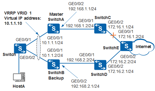
In Figure 1, hosts on a LAN are dual-homed to SwitchA and SwitchB through the switch. A VRRP group is established on SwitchA and SwitchB, and SwitchA is the master. SwitchA functions as the gateway and user traffic is forwarded along the path Switch -> SwitchA -> SwitchC -> SwitchE.
When the route between SwitchC and SwitchE is withdrawn or becomes inactive, the VRRP group can detect the fault and implement a rapid active/standby switchover. Then SwitchB forwards services. This reduces the impact of the link fault on service forwarding.

In this scenario, to avoid loops, ensure that all connected interfaces have STP disabled and connected interfaces are removed from VLAN 1. If STP is enabled and VLANIF interfaces of switches are used to construct a Layer 3 ring network, an interface on the network will be blocked. As a result, Layer 3 services on the network cannot run normally.
Device |
Interface |
VLANIF Interface |
IP Address |
|---|---|---|---|
SwitchA |
GE0/0/1 |
VLANIF 100 |
10.1.1.1/24 |
GE0/0/2 |
VLANIF 300 |
192.168.1.1/24 |
|
SwitchB |
GE0/0/1 |
VLANIF 100 |
10.1.1.2/24 |
GE0/0/2 |
VLANIF 200 |
192.168.2.1/24 |
|
SwitchC |
GE0/0/1 |
VLANIF 300 |
192.168.1.2/24 |
GE0/0/2 |
VLANIF 500 |
172.16.1.1/24 |
|
SwitchD |
GE0/0/1 |
VLANIF 200 |
192.168.2.2/24 |
GE0/0/2 |
VLANIF 400 |
172.16.2.1/24 |
|
SwitchE |
GE0/0/1 |
VLANIF 500 |
172.16.1.2/24 |
GE0/0/2 |
VLANIF 400 |
172.16.2.2/24 |
Configuration Roadmap
The configuration roadmap is as follows:
- Assign an IP address to each interface and configure a routing protocol to ensure network connectivity.
- Configure a VRRP group on SwitchA and SwitchB, set the preemption delay to 20s and a higher priority for SwitchA so that SwitchA functions as the master to forward traffic, and set a lower priority for SwitchB so that SwitchB functions as the backup.
- Configure association between VRRP and routing on SwitchA to implement a fast active/standby switchover if the monitored route is withdrawn or becomes inactive.
Procedure
- Assign an IP address to each interface. SwitchA is used as an example. The configurations of SwitchB, SwitchC, SwitchD, and SwitchE are similar to the configuration of SwitchA. For details, see the configuration files.
<HUAWEI> system-view
[HUAWEI] sysname SwitchA
[SwitchA] vlan batch 100 300
[SwitchA] interface gigabitethernet 0/0/1
[SwitchA-GigabitEthernet0/0/1] port link-type trunk
[SwitchA-GigabitEthernet0/0/1] port trunk allow-pass vlan 100
[SwitchA-GigabitEthernet0/0/1] port trunk pvid vlan 100
[SwitchA-GigabitEthernet0/0/1] undo port trunk allow-pass vlan 1
[SwitchA-GigabitEthernet0/0/1] quit
[SwitchA] interface gigabitethernet 0/0/2
[SwitchA-GigabitEthernet0/0/2] port link-type trunk
[SwitchA-GigabitEthernet0/0/2] port trunk allow-pass vlan 300
[SwitchA-GigabitEthernet0/0/2] quit
[SwitchA] interface vlanif 100
[SwitchA-Vlanif100] ip address 10.1.1.1 24
[SwitchA-Vlanif100] quit
[SwitchA] interface vlanif 300
[SwitchA-Vlanif300] ip address 192.168.1.1 24
[SwitchA-Vlanif300] quit
- Configure Layer 2 transmission on the switch.
<HUAWEI> system-view
[HUAWEI] sysname Switch
[Switch] vlan 100
[Switch-vlan100] quit
[Switch] interface gigabitethernet 0/0/1
[Switch-GigabitEthernet0/0/1] port link-type trunk
[Switch-GigabitEthernet0/0/1] port trunk allow-pass vlan 100
[Switch-GigabitEthernet0/0/1] port trunk pvid vlan 100
[Switch-GigabitEthernet0/0/1] undo port trunk allow-pass vlan 1
[Switch-GigabitEthernet0/0/1] quit
[Switch] interface gigabitethernet 0/0/2
[Switch-GigabitEthernet0/0/2] port link-type trunk
[Switch-GigabitEthernet0/0/2] port trunk allow-pass vlan 100
[Switch-GigabitEthernet0/0/2] port trunk pvid vlan 100
[Switch-GigabitEthernet0/0/2] undo port trunk allow-pass vlan 1
[Switch-GigabitEthernet0/0/2] quit
- Configure VRRP groups.
# Configure VRRP group 1 on SwitchA, and set the priority of SwitchA to 120 and the preemption delay to 20s.
[SwitchA] interface vlanif 100
[SwitchA-Vlanif100] vrrp vrid 1 virtual-ip 10.1.1.10
[SwitchA-Vlanif100] vrrp vrid 1 priority 120
[SwitchA-Vlanif100] vrrp vrid 1 preempt-mode timer delay 20
[SwitchA-Vlanif100] quit
# Configure VRRP group 1 on SwitchB, and set the default priority of 100 for SwitchB.
[SwitchB] interface vlanif 100
[SwitchB-Vlanif100] vrrp vrid 1 virtual-ip 10.1.1.10
[SwitchB-Vlanif100] quit
- Configure IS-IS. SwitchA, SwitchC, and SwitchE are used as an example. The configurations of SwitchB and SwitchD are similar to the configuration of SwitchA. For details, see the configuration files.
# Set the IS-IS NET of SwitchA to 10.0000.0000.0001.00, and set the IS-IS level to 1.
[SwitchA] isis 1
[SwitchA-isis-1] is-level level-1
[SwitchA-isis-1] network-entity 10.0000.0000.0001.00
[SwitchA-isis-1] quit
[SwitchA] interface vlanif 300
[SwitchA-Vlanif300] isis enable 1
[SwitchA-Vlanif300] quit
# Set the IS-IS NET of SwitchC to 10.0000.0000.0002.00, and set the IS-IS level to 1.
[SwitchC] isis 1
[SwitchC-isis-1] is-level level-1
[SwitchC-isis-1] network-entity 10.0000.0000.0002.00
[SwitchC-isis-1] quit
[SwitchC] interface vlanif 300
[SwitchC-Vlanif300] isis enable 1
[SwitchC-Vlanif300] quit
[SwitchC] interface vlanif 500
[SwitchC-Vlanif500] isis enable 1
[SwitchC-Vlanif500] quit
# Set the IS-IS NET of SwitchE to 10.0000.0000.0003.00 and 20.0000.0000.0003.00, and set the IS-IS level to 1.
[SwitchE] isis 1
[SwitchE-isis-1] is-level level-1
[SwitchE-isis-1] network-entity 10.0000.0000.0003.00
[SwitchE-isis-1] quit
[SwitchE] interface vlanif 500
[SwitchE-Vlanif500] isis enable 1
[SwitchE-Vlanif500] quit
[SwitchE] isis 2
[SwitchE-isis-2] is-level level-1
[SwitchE-isis-2] network-entity 20.0000.0000.0003.00
[SwitchE-isis-2] quit
[SwitchE] interface vlanif 400
[SwitchE-Vlanif400] isis enable 2
[SwitchE-Vlanif400] quit
- Configure association between VRRP and routing on SwitchA. When the associated route is withdrawn, the priority of SwitchA decreases by 40.
[SwitchA] interface vlanif 100
[SwitchA-Vlanif100] vrrp vrid 1 track ip route 172.16.1.0 24 reduced 40
[SwitchA-Vlanif100] quit
- Verify the configuration.
# Run the display isis route command on SwitchA. You can see a route to network segment 172.16.1.0/24.
[SwitchA] display isis route

                         Route information for ISIS(1)
                         -----------------------------

                        ISIS(1) Level-1 Forwarding Table
                        --------------------------------

IPV4 Destination     IntCost    ExtCost ExitInterface   NextHop         Flags
-------------------------------------------------------------------------------
192.168.1.0/24       10         NULL    Vlanif300       Direct          D/-/L/-
172.16.1.0/24        20         NULL    Vlanif300       192.168.1.2     A/-/-/-
     Flags: D-Direct, A-Added to URT, L-Advertised in LSPs, S-IGP Shortcut,
                               U-Up/Down Bit Set
# Run the display vrrp command on SwitchA and SwitchB. You can see that SwitchA is the master, SwitchB is the backup, and the associated route is reachable.
[SwitchA] display vrrp
  Vlanif100 | Virtual Router 1
    State          : Master
    Virtual IP       : 10.1.1.10
    Master IP        : 10.1.1.1
    PriorityRun      : 120
    PriorityConfig   : 120
    MasterPriority   : 120
    Preempt          : YES   Delay Time : 20 s
    TimerRun         : 1 s
    TimerConfig      : 1 s
    Auth type        : NONE
    Virtual MAC      :  0000-5e00-0101
    Check TTL        : YES
    Config type      : normal-vrrp
    Backup-forward   : disabled
    Track IP route : 172.16.1.0/24  Priority reduced : 40
    IP route state : Reachable
    Create time : 2012-05-29 21:25:47
    Last change time : 2012-05-29 21:25:51
[SwitchB] display vrrp
  Vlanif100 | Virtual Router 1
    State          : Backup
    Virtual IP       : 10.1.1.10
    Master IP        : 10.1.1.1
    PriorityRun      : 100
    PriorityConfig   : 100
    MasterPriority   : 120
    Preempt          : YES   Delay Time : 0 s
    TimerRun         : 1 s
    TimerConfig      : 1 s
    Auth type        : NONE
    Virtual MAC      :  0000-5e00-0101
    Check TTL        : YES
    Config type      : normal-vrrp
    Backup-forward   : disabled
    Create time : 2012-05-29 21:25:47
    Last change time : 2012-05-29 21:25:51
# Run the shutdown command on GE0/0/1 of SwitchE to simulate a link fault.
[SwitchE] interface gigabitethernet 0/0/1
[SwitchE-GigabitEthernet0/0/1] shutdown
[SwitchE-GigabitEthernet0/0/1] quit
# Run the display isis route command on SwitchA. You can see that the route to network segment 172.16.1.0/24 is withdrawn.
[SwitchA] display isis route

                         Route information for ISIS(1)
                         -----------------------------

                        ISIS(1) Level-1 Forwarding Table
                        --------------------------------

IPV4 Destination     IntCost    ExtCost ExitInterface   NextHop         Flags
-------------------------------------------------------------------------------
192.168.1.0/24       10         NULL    Vlanif300       Direct          D/-/L/-
     Flags: D-Direct, A-Added to URT, L-Advertised in LSPs, S-IGP Shortcut,
                               U-Up/Down Bit Set
# Run the display vrrp command on SwitchA and SwitchB. You can see that SwitchA transitions to the Backup state, SwitchB transitions to the Master state, and the associated route is unreachable.
[SwitchA] display vrrp
  Vlanif100 | Virtual Router 1
    State          : Backup
    Virtual IP       : 10.1.1.10
    Master IP        : 10.1.1.2
    PriorityRun      : 80
    PriorityConfig   : 120
    MasterPriority   : 100
    Preempt          : YES   Delay Time : 20 s
    TimerRun         : 1 s
    TimerConfig      : 1 s
    Auth type        : NONE
    Virtual MAC      :  0000-5e00-0101
    Check TTL        : YES
    Config type      : normal-vrrp
    Backup-forward   : disabled
    Track IP route : 172.16.1.0/24  Priority reduced : 40
    IP route state : Unreachable
    Create time : 2012-05-29 21:25:47
    Last change time : 2012-05-29 21:25:51
[SwitchB] display vrrp
  Vlanif100 | Virtual Router 1
    State          : Master
    Virtual IP       : 10.1.1.10
    Master IP        : 10.1.1.2
    PriorityRun      : 100
    PriorityConfig   : 100
    MasterPriority   : 100
    Preempt          : YES   Delay Time : 0 s
    TimerRun         : 1 s
    TimerConfig      : 1 s
    Auth type        : NONE
    Virtual MAC      :  0000-5e00-0101
    Check TTL        : YES
    Config type      : normal-vrrp
    Backup-forward   : disabled
    Create time : 2012-05-29 21:25:47
    Last change time : 2012-05-29 21:25:51
# Run the undo shutdown command on GE0/0/1 of SwitchE.
[SwitchE] interface gigabitethernet 0/0/1
[SwitchE-GigabitEthernet0/0/1] undo shutdown
[SwitchE-GigabitEthernet0/0/1] quit
# After 20s, run the display vrrp command on SwitchA and SwitchB. You can see that SwitchA is the master, SwitchB is the backup, and the associated route is reachable.
[SwitchA] display vrrp
  Vlanif100 | Virtual Router 1
    State          : Master
    Virtual IP       : 10.1.1.10
    Master IP        : 10.1.1.1
    PriorityRun      : 120
    PriorityConfig   : 120
    MasterPriority   : 120
    Preempt          : YES   Delay Time : 20 s
    TimerRun         : 1 s
    TimerConfig      : 1 s
    Auth type        : NONE
    Virtual MAC      :  0000-5e00-0101
    Check TTL        : YES
    Config type      : normal-vrrp
    Backup-forward   : disabled
    Track IP route : 172.16.1.0/24  Priority reduced : 40
    IP route state : Reachable
    Create time : 2012-05-29 21:27:47
    Last change time : 2012-05-29 21:27:51
[SwitchB] display vrrp
  Vlanif100 | Virtual Router 1
    State          : Backup
    Virtual IP       : 10.1.1.10
    Master IP        : 10.1.1.1
    PriorityRun      : 100
    PriorityConfig   : 100
    MasterPriority   : 120
    Preempt          : YES   Delay Time : 0 s
    TimerRun         : 1 s
    TimerConfig      : 1 s
    Auth type        : NONE
    Virtual MAC      :  0000-5e00-0101
    Check TTL        : YES
    Config type      : normal-vrrp
    Backup-forward   : disabled
    Create time : 2012-05-29 21:27:47
    Last change time : 2012-05-29 21:27:51
Configuration Files
SwitchA configuration file
#
sysname SwitchA
#
vlan batch 100 300
#
isis 1
 is-level level-1
 network-entity 10.0000.0000.0001.00
#
interface Vlanif100
 ip address 10.1.1.1 255.255.255.0
 vrrp vrid 1 virtual-ip 10.1.1.10
 vrrp vrid 1 priority 120
 vrrp vrid 1 preempt-mode timer delay 20
 vrrp vrid 1 track ip route 172.16.1.0 255.255.255.0 reduced 40
#
interface Vlanif300
 ip address 192.168.1.1 255.255.255.0
 isis enable 1
#
interface GigabitEthernet0/0/1
 port link-type trunk
 port trunk pvid vlan 100
 undo port trunk allow-pass vlan 1
 port trunk allow-pass vlan 100
#
interface GigabitEthernet0/0/2
 port link-type trunk
 port trunk allow-pass vlan 300
#
 return
SwitchB configuration file
#
sysname SwitchB
#
vlan batch 100 200
#
isis 2
 is-level level-1
 network-entity 20.0000.0000.0001.00
#
interface Vlanif100
 ip address 10.1.1.2 255.255.255.0
 vrrp vrid 1 virtual-ip 10.1.1.10
#
interface Vlanif200
 ip address 192.168.2.1 255.255.255.0
 isis enable 2
#
interface GigabitEthernet0/0/1
 port link-type trunk
 port trunk pvid vlan 100
 undo port trunk allow-pass vlan 1
 port trunk allow-pass vlan 100
#
interface GigabitEthernet0/0/2
 port link-type trunk
 port trunk allow-pass vlan 200
#
 return
SwitchC configuration file
#
sysname SwitchC
#
vlan batch 300 500
#
isis 1
 is-level level-1
 network-entity 10.0000.0000.0002.00
#
interface Vlanif300
 ip address 192.168.1.2 255.255.255.0
 isis enable 1
#
interface Vlanif500
 ip address 172.16.1.1 255.255.255.0
 isis enable 1
#
interface GigabitEthernet0/0/1
 port link-type trunk
 port trunk allow-pass vlan 300
#
interface GigabitEthernet0/0/2
 port link-type trunk
 port trunk allow-pass vlan 500
#
 return
SwitchD configuration file
#
sysname SwitchD
#
vlan batch 200 400
#
isis 2
 is-level level-1
 network-entity 20.0000.0000.0002.00
#
interface Vlanif200
 ip address 192.168.2.2 255.255.255.0
 isis enable 2
#
interface Vlanif400
 ip address 172.16.2.1 255.255.255.0
 isis enable 2
#
interface GigabitEthernet0/0/1
 port link-type trunk
 port trunk allow-pass vlan 200
#
interface GigabitEthernet0/0/2
 port link-type trunk
 port trunk allow-pass vlan 400
#
 return
SwitchE configuration file
#
sysname SwitchE
#
vlan batch 400 500
#
isis 1
 is-level level-1
 network-entity 10.0000.0000.0003.00
#
isis 2
 is-level level-1
 network-entity 20.0000.0000.0003.00
#
interface Vlanif400
 ip address 172.16.2.2 255.255.255.0
 isis enable 2
#
interface Vlanif500
 ip address 172.16.1.2 255.255.255.0
 isis enable 1
#
interface GigabitEthernet0/0/1
 port link-type trunk
 port trunk allow-pass vlan 500
#
interface GigabitEthernet0/0/2
 port link-type trunk
 port trunk allow-pass vlan 400
#
 return
Switch configuration file
#
sysname Switch
#
vlan batch 100
#
interface GigabitEthernet0/0/1
 port link-type trunk
 port trunk pvid vlan 100
 undo port trunk allow-pass vlan 1
 port trunk allow-pass vlan 100
#
interface GigabitEthernet0/0/2
 port link-type trunk
 port trunk pvid vlan 100
 undo port trunk allow-pass vlan 1
 port trunk allow-pass vlan 100
#
 return