Example for Configuring Association Between VRRP and NQA to Monitor the Uplink Status
Networking Requirements
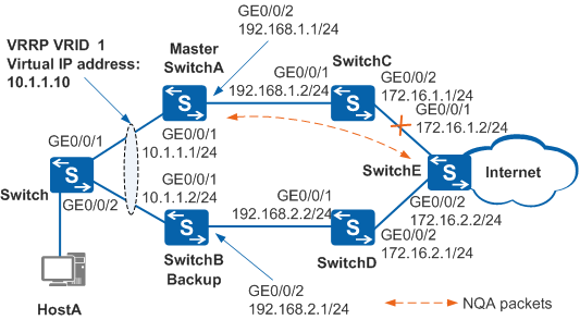
In Figure 1, hosts on a LAN are dual-homed to SwitchA and SwitchB through the switch. A VRRP group is established on SwitchA and SwitchB, and SwitchA is the master. Generally, SwitchA functions as the gateway and user traffic is along the path Switch -> SwitchA -> SwitchC -> SwitchE.
When the link between SwitchC and SwitchE is faulty, the VRRP group can detect the fault within 1s and implement a rapid active/standby switchover. Then SwitchB forwards services. This reduces the impact of the link fault on service forwarding.

In this scenario, to avoid loops, ensure that all connected interfaces have STP disabled and connected interfaces are removed from VLAN 1. If STP is enabled and VLANIF interfaces of switches are used to construct a Layer 3 ring network, an interface on the network will be blocked. As a result, Layer 3 services on the network cannot run normally.
Device |
Interface |
VLANIF Interface |
IP Address |
|---|---|---|---|
SwitchA |
GE0/0/1 |
VLANIF 100 |
10.1.1.1/24 |
GE0/0/2 |
VLANIF 300 |
192.168.1.1/24 |
|
SwitchB |
GE0/0/1 |
VLANIF 100 |
10.1.1.2/24 |
GE0/0/2 |
VLANIF 200 |
192.168.2.1/24 |
|
SwitchC |
GE0/0/1 |
VLANIF 300 |
192.168.1.2/24 |
GE0/0/2 |
VLANIF 500 |
172.16.1.1/24 |
|
SwitchD |
GE0/0/1 |
VLANIF 200 |
192.168.2.2/24 |
GE0/0/2 |
VLANIF 400 |
172.16.2.1/24 |
|
SwitchE |
GE0/0/1 |
VLANIF 500 |
172.16.1.2/24 |
GE0/0/2 |
VLANIF 400 |
172.16.2.2/24 |
Configuration Roadmap
The configuration roadmap is as follows:
- Assign an IP address to each interface and configure a routing protocol to ensure network connectivity.
- Configure a VRRP group on SwitchA and SwitchB. Set the priority of SwitchA to 120 and the preemption delay to 20s so that SwitchA functions as the master. Configure SwitchB to use the default priority so that SwitchB functions as the backup.
- Configure an NQA test instance of ICMP on SwitchA, specify the IP address of GE0/0/1 on SwitchE as the destination address, and configure the NQA test instance to detect connectivity of the link between SwitchA and SwitchE.
- Configure association between VRRP and NQA on SwitchA to implement a rapid active/standby switchover if the link is faulty.
Procedure
- Configure devices to ensure network connectivity.
# Assign an IP address to each interface. SwitchA is used as an example. The configurations of SwitchB, SwitchC, SwitchD, and SwitchE are similar to the configuration of SwitchA. For details, see the configuration files.
<HUAWEI> system-view
[HUAWEI] sysname SwitchA
[SwitchA] vlan batch 100 300
[SwitchA] interface gigabitethernet 0/0/1
[SwitchA-GigabitEthernet0/0/1] port link-type trunk
[SwitchA-GigabitEthernet0/0/1] port trunk allow-pass vlan 100
[SwitchA-GigabitEthernet0/0/1] port trunk pvid vlan 100
[SwitchA-GigabitEthernet0/0/1] undo port trunk allow-pass vlan 1
[SwitchA-GigabitEthernet0/0/1] quit
[SwitchA] interface gigabitethernet 0/0/2
[SwitchA-GigabitEthernet0/0/2] port link-type trunk
[SwitchA-GigabitEthernet0/0/2] port trunk allow-pass vlan 300
[SwitchA-GigabitEthernet0/0/2] quit
[SwitchA] interface vlanif 100
[SwitchA-Vlanif100] ip address 10.1.1.1 24
[SwitchA-Vlanif100] quit
[SwitchA] interface vlanif 300
[SwitchA-Vlanif300] ip address 192.168.1.1 24
[SwitchA-Vlanif300] quit
# Configure Layer 2 transmission on the switch.
<HUAWEI> system-view
[HUAWEI] sysname Switch
[Switch] vlan 100
[Switch-vlan100] quit
[Switch] interface gigabitethernet 0/0/1
[Switch-GigabitEthernet0/0/1] port link-type trunk
[Switch-GigabitEthernet0/0/1] port trunk allow-pass vlan 100
[Switch-GigabitEthernet0/0/1] port trunk pvid vlan 100
[Switch-GigabitEthernet0/0/1] undo port trunk allow-pass vlan 1
[Switch-GigabitEthernet0/0/1] quit
[Switch] interface gigabitethernet 0/0/2
[Switch-GigabitEthernet0/0/2] port link-type trunk
[Switch-GigabitEthernet0/0/2] port trunk allow-pass vlan 100
[Switch-GigabitEthernet0/0/2] port trunk pvid vlan 100
[Switch-GigabitEthernet0/0/2] undo port trunk allow-pass vlan 1
[Switch-GigabitEthernet0/0/2] quit
# Configure OSPF between devices. SwitchA is used as an example. The configurations of SwitchB, SwitchC, SwitchD, and SwitchE are similar to the configuration of SwitchA. For details, see the configuration files.
[SwitchA] ospf 1
[SwitchA-ospf-1] area 0
[SwitchA-ospf-1-area-0.0.0.0] network 10.1.1.0 0.0.0.255
[SwitchA-ospf-1-area-0.0.0.0] network 192.168.1.0 0.0.0.255
[SwitchA-ospf-1-area-0.0.0.0] quit
[SwitchA-ospf-1] quit
- Configure VRRP groups.
# Configure VRRP group 1 on SwitchA, and set the priority of SwitchA to 120 and the preemption delay to 20s.
[SwitchA] interface vlanif 100
[SwitchA-Vlanif100] vrrp vrid 1 virtual-ip 10.1.1.10
[SwitchA-Vlanif100] vrrp vrid 1 priority 120
[SwitchA-Vlanif100] vrrp vrid 1 preempt-mode timer delay 20
[SwitchA-Vlanif100] quit
# Configure VRRP group 1 on SwitchB, and set the default priority of 100 for SwitchB.
[SwitchB] interface vlanif 100
[SwitchB-Vlanif100] vrrp vrid 1 virtual-ip 10.1.1.10
[SwitchB-Vlanif100] quit
- Configure an NQA test instance.
# Configure an NQA test instance of ICMP with destination IP address 172.16.1.2/24 on SwitchA.
[SwitchA] nqa test-instance user test
[SwitchA-nqa-user-test] test-type icmp
[SwitchA-nqa-user-test] destination-address ipv4 172.16.1.2
[SwitchA-nqa-user-test] frequency 15
[SwitchA-nqa-user-test] start now
[SwitchA-nqa-user-test] quit
# Run the display nqa results test-instance user test command on SwitchA. The command output shows that the NQA test instance status is success.
[SwitchA] display nqa results test-instance user test NQA entry(user, test) :testflag is active ,testtype is icmp 1 . Test 1 result The test is finished Send operation times: 3 Receive response times: 2 Completion:success RTD OverThresholds number: 0 Attempts number:1 Drop operation number:0 Disconnect operation number:0 Operation timeout number:1 System busy operation number:0 Connection fail number:0 Operation sequence errors number:0 RTT Status errors number:0 Destination ip address:172.16.1.2 Min/Max/Average Completion Time: 6/6/6 Sum/Square-Sum Completion Time: 12/72 Last Good Probe Time: 2012-05-22 17:32:56.1 Lost packet ratio: 33 % - Configure association between VRRP and NQA.
# Configure association between VRRP and NQA on SwitchA. When the NQA test instance fails, the priority of SwitchA decreases by 40.
[SwitchA] interface vlanif 100
[SwitchA-Vlanif100] vrrp vrid 1 track nqa user test reduced 40
[SwitchA-Vlanif100] quit
- Verify the configuration.
# Run the display vrrp command on SwitchA and SwitchB. You can see that SwitchA is the master, SwitchB is the backup, and the associated NQA test instance is in success state.
[SwitchA] display vrrp
  Vlanif100 | Virtual Router 1
    State          : Master
    Virtual IP       : 10.1.1.10
    Master IP        : 10.1.1.1
    PriorityRun      : 120
    PriorityConfig   : 120
    MasterPriority   : 120
    Preempt          : YES   Delay Time : 20 s
    TimerRun         : 1 s
    TimerConfig      : 1 s
    Auth type        : NONE
    Virtual MAC      : 0000-5e00-0101
    Check TTL        : YES
    Config type      : normal-vrrp
    Backup-forward   : disabled
    Track NQA : user  test   Priority reduced : 40
    NQA state : success
    Create time      : 2012-05-22 17:32:56
    Last change time : 2012-05-22 17:33:00
[SwitchB] display vrrp
  Vlanif100 | Virtual Router 1
    State          : Backup
    Virtual IP       : 10.1.1.10
    Master IP        : 10.1.1.1
    PriorityRun      : 100
    PriorityConfig   : 100
    MasterPriority   : 120
    Preempt          : YES   Delay Time : 0 s
    TimerRun         : 1 s
    TimerConfig      : 1 s
    Auth type        : NONE
    Virtual MAC      : 0000-5e00-0101
    Check TTL        : YES
    Config type      : normal-vrrp
    Backup-forward   : disabled
    Create time      : 2012-05-22 17:33:00
    Last change time : 2012-05-22 17:33:04
# Run the shutdown command on GE0/0/1 of SwitchE to simulate a link fault.
[SwitchE] interface gigabitethernet 0/0/1
[SwitchE-GigabitEthernet0/0/1] shutdown
[SwitchE-GigabitEthernet0/0/1] quit
# Run the display vrrp command on SwitchA and SwitchB. You can see that SwitchA transitions to the Backup state, SwitchB transitions to the Master state, and the NQA test instance is in failed state.
[SwitchA] display vrrp
  Vlanif100 | Virtual Router 1
    State          : Backup
    Virtual IP       : 10.1.1.10
    Master IP        : 10.1.1.2
    PriorityRun      : 80
    PriorityConfig   : 120
    MasterPriority   : 100
    Preempt          : YES   Delay Time : 20 s
    TimerRun         : 1 s
    TimerConfig      : 1 s
    Auth type        : NONE
    Virtual MAC      : 0000-5e00-0101
    Check TTL        : YES
    Config type      : normal-vrrp
    Backup-forward   : disabled
    Track NQA : user  test   Priority reduced : 40
    NQA state : failed
    Create time      : 2012-05-22 17:34:56
    Last change time : 2012-05-22 17:35:00
[SwitchB] display vrrp
  Vlanif100 | Virtual Router 1
    State          : Master
    Virtual IP       : 10.1.1.10
    Master IP        : 10.1.1.2
    PriorityRun      : 100
    PriorityConfig   : 100
    MasterPriority   : 100
    Preempt          : YES   Delay Time : 0 s
    TimerRun         : 1 s
    TimerConfig      : 1 s
    Auth type        : NONE
    Virtual MAC      : 0000-5e00-0101
    Check TTL        : YES
    Config type      : normal-vrrp
    Backup-forward   : disabled
    Create time      : 2012-05-22 17:35:00
    Last change time : 2012-05-22 17:35:04
# Run the undo shutdown command on GE0/0/1 of SwitchE.
[SwitchE] interface gigabitethernet 0/0/1
[SwitchE-GigabitEthernet0/0/1] undo shutdown
[SwitchE-GigabitEthernet0/0/1] quit
# After 20s, run the display vrrp command on SwitchA and SwitchB. You can see that SwitchA is the master, SwitchB is the backup, and the associated NQA test instance is in success state.
[SwitchA] display vrrp
  Vlanif100 | Virtual Router 1
    State          : Master
    Virtual IP       : 10.1.1.10
    Master IP        : 10.1.1.1
    PriorityRun      : 120
    PriorityConfig   : 120
    MasterPriority   : 120
    Preempt          : YES   Delay Time : 20 s
    TimerRun         : 1 s
    TimerConfig      : 1 s
    Auth type        : NONE
    Virtual MAC      :  0000-5e00-0101
    Check TTL        : YES
    Config type      : normal-vrrp
    Backup-forward   : disabled
    Track NQA : user  test   Priority reduced : 40
    NQA state : success
    Create time      : 2012-05-22 17:36:56
    Last change time : 2012-05-22 17:37:00
[SwitchB] display vrrp
  Vlanif100 | Virtual Router 1
    State          : Backup
    Virtual IP       : 10.1.1.10
    Master IP        : 10.1.1.1
    PriorityRun      : 100
    PriorityConfig   : 100
    MasterPriority   : 120
    Preempt          : YES   Delay Time : 0 s
    TimerRun         : 1 s
    TimerConfig      : 1 s
    Auth type        : NONE
    Virtual MAC      :  0000-5e00-0101
    Check TTL        : YES
    Config type      : normal-vrrp
    Backup-forward   : disabled
    Create time      : 2012-05-22 17:37:00
    Last change time : 2012-05-22 17:37:04
Configuration Files
SwitchA configuration file
#
sysname SwitchA
#
vlan batch 100 300
#
interface Vlanif100
 ip address 10.1.1.1 255.255.255.0
 vrrp vrid 1 virtual-ip 10.1.1.10
 vrrp vrid 1 priority 120
 vrrp vrid 1 preempt-mode timer delay 20
 vrrp vrid 1 track nqa user test reduced 40
#
interface Vlanif300
 ip address 192.168.1.1 255.255.255.0
#
interface GigabitEthernet0/0/1
 port link-type trunk
 port trunk pvid vlan 100
 undo port trunk allow-pass vlan 1
 port trunk allow-pass vlan 100
#
interface GigabitEthernet0/0/2
 port link-type trunk
 port trunk allow-pass vlan 300
#
ospf 1
 area 0.0.0.0
  network 10.1.1.0 0.0.0.255
  network 192.168.1.0 0.0.0.255
#
nqa test-instance user test
 test-type icmp
 destination-address ipv4 172.16.1.2
 frequency 15
 start now
#
return
SwitchB configuration file
#
sysname SwitchB
#
vlan batch 100 200
#
interface Vlanif100
 ip address 10.1.1.2 255.255.255.0
 vrrp vrid 1 virtual-ip 10.1.1.10
#
interface Vlanif200
 ip address 192.168.2.1 255.255.255.0
#
interface GigabitEthernet0/0/1
 port link-type trunk
 port trunk pvid vlan 100
 undo port trunk allow-pass vlan 1
 port trunk allow-pass vlan 100
#
interface GigabitEthernet0/0/2
 port link-type trunk
 port trunk allow-pass vlan 200
#
ospf 1
 area 0.0.0.0
  network 10.1.1.0 0.0.0.255
  network 192.168.2.0 0.0.0.255
#
return
SwitchC configuration file
#
sysname SwitchC
#
vlan batch 300 500
#
interface Vlanif300
 ip address 192.168.1.2 255.255.255.0
#
interface Vlanif500
 ip address 172.16.1.1 255.255.255.0
#
interface GigabitEthernet0/0/1
 port link-type trunk
 port trunk allow-pass vlan 300
#
interface GigabitEthernet0/0/2
 port link-type trunk
 port trunk allow-pass vlan 500
#
ospf 1
 area 0.0.0.0
  network 172.16.1.0 0.0.0.255
  network 192.168.1.0 0.0.0.255
#
return
SwitchD configuration file
#
sysname SwitchD
#
vlan batch 200 400
#
interface Vlanif200
 ip address 192.168.2.2 255.255.255.0
#
interface Vlanif400
 ip address 172.16.2.1 255.255.255.0
#
interface GigabitEthernet0/0/1
 port link-type trunk
 port trunk allow-pass vlan 200
#
interface GigabitEthernet0/0/2
 port link-type trunk
 port trunk allow-pass vlan 400
#
ospf 1
 area 0.0.0.0
  network 172.16.2.0 0.0.0.255
  network 192.168.2.0 0.0.0.255
#
return
SwitchE configuration file
#
sysname SwitchE
#
vlan batch 400 500
#
interface Vlanif400
 ip address 172.16.2.2 255.255.255.0
#
interface Vlanif500
 ip address 172.16.1.2 255.255.255.0
#
interface GigabitEthernet0/0/1
 port link-type trunk
 port trunk allow-pass vlan 500
#
interface GigabitEthernet0/0/2
 port link-type trunk
 port trunk allow-pass vlan 400
#
ospf 1
 area 0.0.0.0
  network 172.16.1.0 0.0.0.255
  network 172.16.2.0 0.0.0.255
#
return
Switch configuration file
#
sysname Switch
#
vlan batch 100
#
interface GigabitEthernet0/0/1
 port link-type trunk
 port trunk pvid vlan 100
 undo port trunk allow-pass vlan 1
 port trunk allow-pass vlan 100
#
interface GigabitEthernet0/0/2
 port link-type trunk
 port trunk pvid vlan 100
 undo port trunk allow-pass vlan 1
 port trunk allow-pass vlan 100
#
return