< Home

Example for Configuring Multicast VPN Access Through MCE Devices

Multicast VPN Overview

Multicast VPN technology allows multicast services to run on BGP/MPLS IP VPN networks. This technology encapsulates multicast packets from a private network to enable the packets to be forwarded along the multicast distribution tree (MDT) on a public network. When the packets reach the destination network, they are decapsulated and forwarded to receivers as multicast packets of the private network.

Multicast VPN is used to address the following problems occurring during the multicast service deployment on BGP/MPLS IP VPN networks:

  • VPN multicast packets cannot pass the reverse path forwarding (RPF) check on the public network.

    In multicast forwarding, multicast routers perform RPF checks on multicast packets based on the multicast source address and inbound interface. Only multicast packets from the RPF interface are forwarded. Each router needs to know the unicast route to the multicast source. The provider (P) device on a BGP/MPLS IP VPN network does not know the VPN routes; therefore, RPF checks fail on the P device.

  • Overlapping multicast source addresses or group addresses on VPNs lead to inter-VPN communication.

    A BGP/MPLS IP VPN network allows overlapping addresses in sites on each VPN; therefore, the multicast source addresses or group addresses of different VPNs may overlap. A PE device must correctly forward multicast packets from a VPN to only the users at the sites on the same VPN to prevent communication between different VPNs.

  • VPN packets are forwarded in unicast mode on the public network. When the multicast traffic volume is high, loads on the public network increase greatly.

    Multicast technology ensures that each link transmits only one copy of multicast packets. Each device replicates multicast data according to the number of outbound interfaces, and the bandwidth consumed does not increase with the number of receivers. If the public network supports multicast forwarding, multicast packets are replicated only at bifurcation points on the public network. This on-demand replication mechanism reduces loads on the public network and conserves bandwidth.

  • All PE devices on a VPN can receive multicast packets from a multicast source on the same VPN. When the multicast traffic volume is high, loads on the PE devices increase greatly.

    A VPN is composed of multiple sites, each of which connects to a different PE. Some sites may not have receivers. If VPN multicast data is forwarded only to the PE devices with receivers connected, burdens on PE devices are reduced.

Configuration Notes

  • If multicast VPN in multicast domain (MD) mode is used on switches, the PIM-SM SSM model cannot be used on the public network.

  • Multicast VPN cannot be deployed on inter-AS BGP/MPLS IPv4 VPN networks.

  • Multicast VPN cannot be deployed on BGP/MPLS IPv6 VPN networks.

  • Interfaces on the following interface cards cannot be configured as member interfaces of Eth-Trunk multicast loopback interfaces:

    • V200R001 to V200R003: ES0D0G24SA00, ES0D0G24CA00, ES0D0X12SA00, ES1D2G48SBC0, and ES1D2G48TBC0 interface cards for the S7700; EH1D2G24SSA0, EH1D2S24CSA0, EH1D2X12SSA0, EH1D2G48SBC0, and EH1D2G48TBC0 interface cards for the S9700
    • V200R005 to V200R009: X1E series, ES0D0G24SA00, ES0D0G24CA00, ES1D2G48SBC0, and ES1D2G48TBC0 interface cards for the S7700; X1E series, EH1D2G48SBC0, and EH1D2G48TBC0 interface cards for the S9700
  • Applicable products and versions lists applicable products and versions.

    For details about software mappings, visit Hardware Query Tool and search for the desired product model.

Networking Requirements

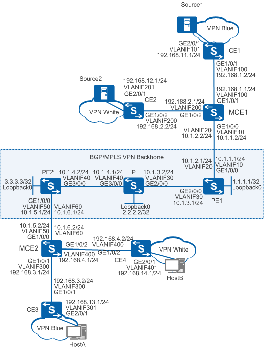
As shown in Figure 1, a company deploys two services, data of which is transmitted in multicast mode. The VPN site blue using service A and the VPN site white using service B both connect to the backbone network through the MCE devices. Multicast VPN in MD mode can be deployed to meet the multicast service requirements of the company. This configuration can isolate data of different services and reduces multicast traffic loads on the public network.

Figure 1 Multicast VPN access through MCE devices

Configuration Roadmap

The configuration roadmap is as follows:

  1. Configure BGP/MPLS IP VPN to ensure connectivity of the VPN network.
  2. Configure multicast loopback interfaces, share-group addresses, and multicast tunnel interfaces (MTIs) for VPN instances on the PE devices to implement multicast VPN in MD mode.
  3. Enable multicast routing and PIM on all the devices. Configure the multicast function in the public network between the PE and P devices. Configure the multicast function in the VPN instances between PE and MCE devices, and between the MCE and CE devices.

Procedure

  1. Configure BGP/MPLS IP VPN.
    1. Configure the Open Shortest Path First (OSPF) protocol on the backbone network to allow communication between the provider edge devices (PE1 and PE2) and intermediate device P.

      # Configure PE1.

      <PE1> system-view
      [PE1] interface loopback 0     //Create a loopback interface.
      [PE1-LoopBack0] ip address 1.1.1.1 32
      [PE1-LoopBack0] quit
      [PE1] router id 1.1.1.1     //Set the router ID of PE1 to 1.1.1.1 for route management.
      [PE1] vlan batch 30
      [PE1] interface gigabitethernet 2/0/0
      [PE1-GigabitEthernet2/0/0] port link-type trunk     //Set the link type of the interface to trunk, which is not the default link type.
      [PE1-GigabitEthernet2/0/0] port trunk allow-pass vlan 30
      [PE1-GigabitEthernet2/0/0] quit
      [PE1] interface vlanif 30     //Create a VLANIF interface.
      [PE1-Vlanif30] ip address 10.1.3.1 24
      [PE1-Vlanif30] quit
      [PE1] ospf
      [PE1-ospf-1] area 0
      [PE1-ospf-1-area-0.0.0.0] network 10.1.3.0 0.0.0.255     //Specify that the interface running OSPF is the one connected to the 10.1.3.0 network segment and that the interface belongs to Area 0.
      [PE1-ospf-1-area-0.0.0.0] network 1.1.1.1 0.0.0.0
      [PE1-ospf-1-area-0.0.0.0] quit
      [PE1-ospf-1] quit

      The configurations on P and PE2 are similar to the configuration of PE1, and are not mentioned here.

      After the configuration is complete, OSPF neighbor relationships can be set up between PE1 and P and between P and PE2. Run the display ospf peer command on PE1, P, and PE2, and you can see that the neighbors are in Full state. Run the display ip routing-table command, and you can see that PE devices have learned the routes to Loopback0 of each other.

    2. Enable basic MPLS capabilities and MPLS LDP on the provider edge devices PE1 and PE2 to set up LDP LSPs on the MPLS backbone network.

      # Configure PE1.

      [PE1] mpls lsr-id 1.1.1.1     //Set the LSR ID of PE1 to 1.1.1.1.
      [PE1] mpls     //Enable MPLS globally.
      [PE1-mpls] quit
      [PE1] mpls ldp     //Enable MPLS LDP globally.
      [PE1-mpls-ldp] quit
      [PE1] interface vlanif 30
      [PE1-Vlanif30] mpls     //Enable MPLS on the VLANIF interface.
      [PE1-Vlanif30] mpls ldp     //Enable MPLS LDP on the VLANIF interface.
      [PE1-Vlanif30] quit

      The configurations on P and PE2 are similar to the configuration of PE1, and are not mentioned here.

      After the configuration is complete, LDP sessions can be set up between PE1 and P and between P and PE2. Run the display mpls ldp session command on the PE and P devices, and you can see that LDP session is in Operational state.

    3. Establish a Multiprotocol Interior Border Gateway Protocol (MP-IBGP) peer relationship between the provider edge devices PE1 and PE2.

      # Configure PE1.

      [PE1] bgp 100
      [PE1-bgp] peer 3.3.3.3 as-number 100     //Create BGP peer 3.3.3.3 and set its AS number to 100.
      [PE1-bgp] peer 3.3.3.3 connect-interface loopback 0     //Specify LoopBack0 as the source interface to send BGP packets to BGP peer 3.3.3.3.
      [PE1-bgp] ipv4-family vpnv4     //Enter the BGP-VPNv4 address  family view.
      [PE1-bgp-af-vpnv4] peer 3.3.3.3 enable     //Enable the local switch to exchange BGP-VPNv4 routes with BGP peer 3.3.3.3.
      [PE1-bgp-af-vpnv4] quit
      [PE1-bgp] quit

      # Configure PE2.

      [PE2] bgp 100
      [PE2-bgp] peer 1.1.1.1 as-number 100     //Create BGP peer 1.1.1.1 and set its AS number to 100.
      [PE2-bgp] peer 1.1.1.1 connect-interface loopback 0     //Specify LoopBack0 as the source interface to send BGP packets to 1.1.1.1.
      [PE2-bgp] ipv4-family vpnv4     //Enter the BGP-VPNv4 address  family view.
      [PE2-bgp-af-vpnv4] peer 1.1.1.1 enable     ///Enable the local switch to exchange BGP-VPNv4 routes with BGP peer 1.1.1.1.
      [PE2-bgp-af-vpnv4] quit
      [PE2-bgp] quit

      After the configuration is complete, run the display bgp vpnv4 all peer command on the PE devices. You can see that a BGP peer relationship has been set up between PE1 and PE2 and is in Established state.

    4. Create VPN instances blue and white on the provider edge devices PE1 and PE2, and aggregate egress devices MCE1 and MCE2 for branches, to connect each service site's egress CE to the PE devices through the MCE devices.

      # Configure PE1.

      [PE1] ip vpn-instance blue     //Create VPN instance blue.
      [PE1-vpn-instance-blue] route-distinguisher 100:1     //Set the RD of VPN instance blue to 100:1.
      [PE1-vpn-instance-blue-af-ipv4] vpn-target 111:1 both     //Add 111:1 to the export VPN target list and import VPN target list of VPN instance blue.
      [PE1-vpn-instance-blue-af-ipv4] quit
      [PE1-vpn-instance-blue] quit
      [PE1] ip vpn-instance white     //Create VPN instance white.
      [PE1-vpn-instance-white] route-distinguisher 200:1     //Set the RD of VPN instance white to 200:1.
      [PE1-vpn-instance-white-af-ipv4] vpn-target 222:1 both     //Add 222:1 to the export VPN target list and import VPN target list of VPN instance white.
      [PE1-vpn-instance-white-af-ipv4] quit
      [PE1-vpn-instance-white] quit
      [PE1] vlan batch 10 20
      [PE1] interface gigabitethernet 1/0/0
      [PE1-GigabitEthernet1/0/0] port link-type trunk     //Set the link type of the interface to trunk, which is not the default link type.
      [PE1-GigabitEthernet1/0/0] port trunk allow-pass vlan 10 20
      [PE1-GigabitEthernet1/0/0] quit
      [PE1] interface vlanif 10
      [PE1-Vlanif10] ip binding vpn-instance blue     //Bind VPN instance blue to VLANIF10 so that VLANIF10 becomes a private network interface of VPN instance blue.
      [PE1-Vlanif10] ip address 10.1.1.1 24
      [PE1-Vlanif10] quit
      [PE1] interface vlanif 20
      [PE1-Vlanif20] ip binding vpn-instance white     //Bind VPN instance blue to VLANIF20 so that VLANIF20 becomes a private network interface of VPN instance white.
      [PE1-Vlanif20] ip address 10.1.2.1 24
      [PE1-Vlanif20] quit

      # Configure MCE1.

      [MCE1] ip vpn-instance blue     //Create VPN instance blue.
      [MCE1-vpn-instance-blue] route-distinguisher 100:1     //Set the RD of VPN instance blue to 100:1.
      [MCE1-vpn-instance-blue-af-ipv4] vpn-target 111:1 both     //Add 111:1 to the export VPN target list and import VPN target list of VPN instance blue.
      [MCE1-vpn-instance-blue-af-ipv4] quit
      [MCE1-vpn-instance-blue] quit
      [MCE1] ip vpn-instance white     //Create VPN instance white.
      [MCE1-vpn-instance-white] route-distinguisher 200:1     //Set the RD of VPN instance white to 200:1.
      [MCE1-vpn-instance-white-af-ipv4] vpn-target 222:1 both     //Add 222:1 to the export VPN target list and import VPN target list of VPN instance white.
      [MCE1-vpn-instance-white-af-ipv4] quit
      [MCE1-vpn-instance-white] quit
      [MCE1] vlan batch 10 20 100 200
      [MCE1] interface gigabitethernet 1/0/0
      [MCE1-GigabitEthernet1/0/0] port link-type trunk     //Set the link type of the interface to trunk, which is not the default link type.
      [MCE1-GigabitEthernet1/0/0] port trunk allow-pass vlan 10 20
      [MCE1-GigabitEthernet1/0/0] quit
      [MCE1] interface gigabitethernet 1/0/1
      [MCE1-GigabitEthernet1/0/1] port link-type trunk     //Set the link type of the interface to trunk, which is not the default link type.
      [MCE1-GigabitEthernet1/0/1] port trunk allow-pass vlan 100
      [MCE1-GigabitEthernet1/0/1] quit
      [MCE1] interface gigabitethernet 1/0/2
      [MCE1-GigabitEthernet1/0/2] port link-type trunk     //Set the link type of the interface to trunk, which is not the default link type.
      [MCE1-GigabitEthernet1/0/2] port trunk allow-pass vlan 200
      [MCE1-GigabitEthernet1/0/2] quit
      [MCE1] interface vlanif 10
      [MCE1-Vlanif10] ip binding vpn-instance blue     //Bind VPN instance blue to VLANIF10 so that VLANIF10 becomes a private network interface of VPN instance blue.
      [MCE1-Vlanif10] ip address 10.1.1.2 24
      [MCE1-Vlanif10] quit
      [MCE1] interface vlanif 20
      [MCE1-Vlanif20] ip binding vpn-instance white     //Bind VPN instance white to VLANIF20 so that VLANIF20 becomes a private network interface of VPN instance white.
      [MCE1-Vlanif20] ip address 10.1.2.2 24
      [MCE1-Vlanif20] quit
      [MCE1] interface vlanif 100
      [MCE1-Vlanif100] ip binding vpn-instance blue     //Bind VPN instance blue to VLANIF100 so that VLANIF100 becomes a private network interface of VPN instance blue.
      [MCE1-Vlanif100] ip address 192.168.1.1 24
      [MCE1-Vlanif100] quit
      [MCE1] interface vlanif 200
      [MCE1-Vlanif200] ip binding vpn-instance white     //Bind VPN instance white to VLANIF200 so that VLANIF200 becomes a private network interface of VPN instance white.
      [MCE1-Vlanif200] ip address 192.168.2.1 24
      [MCE1-Vlanif200] quit

      # Configure PE2.

      [PE2] ip vpn-instance blue     //Create VPN instance blue.
      [PE2-vpn-instance-blue] route-distinguisher 100:1     //Set the RD of VPN instance blue to 100:1.
      [PE2-vpn-instance-blue-af-ipv4] vpn-target 111:1 both     //Add 111:1 to the export VPN target list and import VPN target list of VPN instance blue.
      [PE2-vpn-instance-blue-af-ipv4] quit
      [PE2-vpn-instance-blue] quit
      [PE2] ip vpn-instance white     //Create VPN instance white.
      [PE2-vpn-instance-white] route-distinguisher 200:1     //Set the RD of VPN instance white to 200:1.
      [PE2-vpn-instance-white-af-ipv4] vpn-target 222:1 both     //Add 222:1 to the export VPN target list and import VPN target list of VPN instance white.
      [PE2-vpn-instance-white-af-ipv4] quit
      [PE2-vpn-instance-white] quit
      [PE2] vlan batch 50 60
      [PE2] interface gigabitethernet 1/0/0
      [PE2-GigabitEthernet1/0/0] port link-type trunk     //Set the link type of the interface to trunk, which is not the default link type.
      [PE2-GigabitEthernet1/0/0] port trunk allow-pass vlan 50 60
      [PE2-GigabitEthernet1/0/0] quit
      [PE2] interface vlanif 50
      [PE2-Vlanif50] ip binding vpn-instance blue     //Bind VPN instance blue to VLANIF50 so that VLANIF50 becomes a private network interface of VPN instance blue.
      [PE2-Vlanif50] ip address 10.1.5.1 24
      [PE2-Vlanif50] quit
      [PE2] interface vlanif 60
      [PE2-Vlanif60] ip binding vpn-instance white     //Bind VPN instance white to VLANIF60 so that VLANIF60 becomes a private network interface of VPN instance white.
      [PE2-Vlanif60] ip address 10.1.6.1 24
      [PE2-Vlanif60] quit

      # Configure MCE2.

      [MCE2] ip vpn-instance blue     //Create VPN instance blue.
      [MCE2-vpn-instance-blue] route-distinguisher 100:1     //Set the RD of VPN instance blue to 100:1.
      [MCE2-vpn-instance-blue-af-ipv4] vpn-target 111:1 both     //Add 111:1 to the export VPN target list and import VPN target list of VPN instance blue.
      [MCE2-vpn-instance-blue-af-ipv4] quit
      [MCE2-vpn-instance-blue] quit
      [MCE2] ip vpn-instance white     //Create VPN instance white.
      [MCE2-vpn-instance-white] route-distinguisher 200:1     //Set the RD of VPN instance white to 200:1.
      [MCE2-vpn-instance-white-af-ipv4] vpn-target 222:1 both     //Add 222:1 to the export VPN target list and import VPN target list of VPN instance white.
      [MCE2-vpn-instance-white-af-ipv4] quit
      [MCE2-vpn-instance-white] quit
      [MCE2] vlan batch 50 60 300 400
      [MCE2] interface gigabitethernet 1/0/0
      [MCE2-GigabitEthernet1/0/0] port link-type trunk     //Set the link type of the interface to trunk, which is not the default link type.
      [MCE2-GigabitEthernet1/0/0] port trunk allow-pass vlan 50 60
      [MCE2-GigabitEthernet1/0/0] quit
      [MCE2] interface gigabitethernet 1/0/1
      [MCE2-GigabitEthernet1/0/1] port link-type trunk     //Set the link type of the interface to trunk, which is not the default link type.
      [MCE2-GigabitEthernet1/0/1] port trunk allow-pass vlan 300
      [MCE2-GigabitEthernet1/0/1] quit
      [MCE2] interface gigabitethernet 1/0/2
      [MCE2-GigabitEthernet1/0/2] port link-type trunk     //Set the link type of the interface to trunk, which is not the default link type.
      [MCE2-GigabitEthernet1/0/2] port trunk allow-pass vlan 400
      [MCE2-GigabitEthernet1/0/2] quit
      [MCE2] interface vlanif 50
      [MCE2-Vlanif50] ip binding vpn-instance blue     //Bind VPN instance blue to VLANIF50 so that VLANIF50 becomes a private network interface of VPN instance blue.
      [MCE2-Vlanif50] ip address 10.1.5.2 24
      [MCE2-Vlanif50] quit
      [MCE2] interface vlanif 60
      [MCE2-Vlanif60] ip binding vpn-instance white     //Bind VPN instance white to VLANIF60 so that VLANIF60 becomes a private network interface of VPN instance white.
      [MCE2-Vlanif60] ip address 10.1.6.2 24
      [MCE2-Vlanif60] quit
      [MCE2] interface vlanif 300
      [MCE2-Vlanif300] ip binding vpn-instance blue     //Bind VPN instance blue to VLANIF300 so that VLANIF300 becomes a private network interface of VPN instance blue.
      [MCE2-Vlanif300] ip address 192.168.3.1 24
      [MCE2-Vlanif300] quit
      [MCE2] interface vlanif 400
      [MCE2-Vlanif400] ip binding vpn-instance white     //Bind VPN instance white to VLANIF400 so that VLANIF400 becomes a private network interface of VPN instance white.
      [MCE2-Vlanif400] ip address 192.168.4.1 24
      [MCE2-Vlanif400] quit

    5. Configure OSPF on the provider edge devices PE1 and PE2, branches' aggregate egress devices MCE1 and MCE2, and each service site's egress CE. Import VPN routes to the OSPF routing table.

      # Configure PE1.

      [PE1] ospf 2 vpn-instance blue     //Create an OSPF process to serve VPN instance blue.
      [PE1-ospf-2] import-route bgp     //Import BGP routes.
      [PE1-ospf-2] area 0
      [PE1-ospf-2-area-0.0.0.0] network 10.1.1.0 0.0.0.255     //Specify that the interface running OSPF is the one connected to the 10.1.1.0 network segment and that the interface belongs to Area 0.
      [PE1-ospf-2-area-0.0.0.0] quit
      [PE1-ospf-2] quit
      [PE1] ospf 3 vpn-instance white     //Create an OSPF process to serve VPN instance white.
      [PE1-ospf-3] import-route bgp     //Import BGP routes.
      [PE1-ospf-3] area 0
      [PE1-ospf-3-area-0.0.0.0] network 10.1.2.0 0.0.0.255     //Specify that the interface running OSPF is the one connected to the 10.1.2.0 network segment and that the interface belongs to Area 0.
      [PE1-ospf-3-area-0.0.0.0] quit
      [PE1-ospf-3] quit
      [PE1] bgp 100
      [PE1-bgp] ipv4-family vpn-instance blue     //Enter the IPv4 address family view of BGP-VPN instance blue.
      [PE1-bgp-blue] import-route ospf 2     //Import routes of OSPF process 2.
      [PE1-bgp-blue] quit
      [PE1-bgp] ipv4-family vpn-instance white     //Enter the IPv4 address family view of BGP-VPN instance white
      [PE1-bgp-white] import-route ospf 3     //Import routes of OSPF process 3.
      [PE1-bgp-white] quit
      [PE1-bgp] quit

      # Configure MCE1.

      [MCE1] ospf 1 vpn-instance blue     //Create an OSPF process to serve VPN instance blue.
      [MCE1-ospf-1] vpn-instance-capability simple     //Disable OSPF routing loop detection.
      [MCE1-ospf-1] area 0
      [MCE1-ospf-1-area-0.0.0.0] network 10.1.1.0 0.0.0.255     //Specify that the interface is running OSPF is the one connected to the 10.1.1.0 network segment and that the interface belongs to Area 0.
      [MCE1-ospf-1-area-0.0.0.0] network 192.168.1.0 0.0.0.255     //Specify that the interface is running OSPF is the one connected to the 192.168.1.0 network segment and that the interface belongs to Area 0.
      [MCE1-ospf-1-area-0.0.0.0] quit
      [MCE1-ospf-1] quit
      [MCE1] ospf 2 vpn-instance white     //Create an OSPF process to serve VPN instance white.
      [MCE1-ospf-2] vpn-instance-capability simple     //Disable OSPF routing loop detection.
      [MCE1-ospf-2] area 0
      [MCE1-ospf-2-area-0.0.0.0] network 10.1.2.0 0.0.0.255     //Specify that the interface is running OSPF is the one connected to the 10.1.2.0 network segment and that the interface belongs to Area 0.
      [MCE1-ospf-2-area-0.0.0.0] network 192.168.2.0 0.0.0.255     //Specify that the interface is running OSPF is the one connected to the 192.168.2.0 network segment and that the interface belongs to Area 0.
      [MCE1-ospf-2-area-0.0.0.0] quit
      [MCE1-ospf-2] quit

      # Configure PE2.

      [PE2] ospf 2 vpn-instance blue     //Create an OSPF process to serve VPN instance blue.
      [PE2-ospf-2] import-route bgp     //Import BGP routes.
      [PE2-ospf-2] area 0
      [PE2-ospf-2-area-0.0.0.0] network 10.1.5.0 0.0.0.255     //Specify that the interface is running OSPF is the one connected to the 10.1.5.0 network segment and that the interface belongs to Area 0.
      [PE2-ospf-2-area-0.0.0.0] quit
      [PE2-ospf-2] quit
      [PE2] ospf 3 vpn-instance white     //Create an OSPF process to serve VPN instance white.
      [PE2-ospf-3] import-route bgp     //Import BGP routes.
      [PE2-ospf-3] area 0
      [PE2-ospf-3-area-0.0.0.0] network 10.1.6.0 0.0.0.255     //Specify that the interface is running OSPF is the one connected to the 10.1.6.0 network segment and that the interface belongs to Area 0.
      [PE2-ospf-3-area-0.0.0.0] quit
      [PE2-ospf-3] quit
      [PE2] bgp 100
      [PE2-bgp] ipv4-family vpn-instance blue     //Enter the IPv4 address family view of BGP-VPN instance blue.
      [PE2-bgp-blue] import-route ospf 2     //Import routes of OSPF process 2.
      [PE2-bgp-blue] quit
      [PE2-bgp] ipv4-family vpn-instance white     //Enter the IPv4 address family view of BGP-VPN instance white.
      [PE2-bgp-white] import-route ospf 3     //Import routes of OSPF process 3.
      [PE2-bgp-white] quit
      [PE2-bgp] quit

      # Configure MCE2.

      [MCE2] ospf 1 vpn-instance blue     //Create an OSPF process to serve VPN instance blue.
      [MCE2-ospf-1] vpn-instance-capability simple     //Disable OSPF routing loop detection.
      [MCE2-ospf-1] area 0
      [MCE2-ospf-1-area-0.0.0.0] network 10.1.5.0 0.0.0.255     //Specify that the interface is running OSPF is the one connected to the 10.1.5.0 network segment and that the interface belongs to Area 0.
      [MCE2-ospf-1-area-0.0.0.0] network 192.168.3.0 0.0.0.255     //Specify that the interface is running OSPF is the one connected to the 192.168.3.0 network segment and that the interface belongs to Area 0.
      [MCE2-ospf-1-area-0.0.0.0] quit
      [MCE2-ospf-1] quit
      [MCE2] ospf 2 vpn-instance white     //Create an OSPF process to serve VPN instance white.
      [MCE2-ospf-2] vpn-instance-capability simple     //Disable OSPF routing loop detection.
      [MCE2-ospf-2] area 0
      [MCE2-ospf-2-area-0.0.0.0] network 10.1.6.0 0.0.0.255     //Specify that the interface is running OSPF is the one connected to the 10.1.6.0 network segment and that the interface belongs to Area 0.
      [MCE2-ospf-2-area-0.0.0.0] network 192.168.4.0 0.0.0.255     //Specify that the interface is running OSPF is the one connected to the 192.168.4.0 network segment and that the interface belongs to Area 0.
      [MCE2-ospf-2-area-0.0.0.0] quit
      [MCE2-ospf-2] quit

      # Configure CE1, egress for a site of service A.

      [CE1] vlan batch 100 101
      [CE1] interface gigabitethernet 1/0/1
      [CE1-GigabitEthernet1/0/1] port link-type trunk     //Set the link type of the interface to trunk, which is not the default link type.
      [CE1-GigabitEthernet1/0/1] port trunk allow-pass vlan 100
      [CE1-GigabitEthernet1/0/1] quit
      [CE1] interface gigabitethernet 2/0/1
      [CE1-GigabitEthernet2/0/1] port link-type trunk     //Set the link type of the interface to trunk, which is not the default link type.
      [CE1-GigabitEthernet2/0/1] port trunk allow-pass vlan 101
      [CE1-GigabitEthernet2/0/1] quit
      [CE1] interface vlanif 100
      [CE1-Vlanif100] ip address 192.168.1.2 24
      [CE1-Vlanif100] quit
      [CE1] interface vlanif 101
      [CE1-Vlanif101] ip address 192.168.11.1 24
      [CE1-Vlanif101] quit
      [CE1] ospf
      [CE1-ospf-1] area 0
      [CE1-ospf-1-area-0.0.0.0] network 192.168.1.0 0.0.0.255     //Specify that the interface is running OSPF is the one connected to the 192.168.1.0 network segment and that the interface belongs to Area 0.
      [CE1-ospf-1-area-0.0.0.0] network 192.168.11.0 0.0.0.255     //Specify that the interface is running OSPF is the one connected to the 192.168.11.0 network segment and that the interface belongs to Area 0.
      [CE1-ospf-1-area-0.0.0.0] quit
      [CE1-ospf-1] quit

      # Configure CE2, egress for a site of service B.

      [CE2] vlan batch 200 201
      [CE2] interface gigabitethernet 1/0/2
      [CE2-GigabitEthernet1/0/2] port link-type trunk     //Set the link type of the interface to trunk, which is not the default link type.
      [CE2-GigabitEthernet1/0/2] port trunk allow-pass vlan 200
      [CE2-GigabitEthernet1/0/2] quit
      [CE2] interface gigabitethernet 2/0/1
      [CE2-GigabitEthernet2/0/1] port link-type trunk     //Set the link type of the interface to trunk, which is not the default link type.
      [CE2-GigabitEthernet2/0/1] port trunk allow-pass vlan 201
      [CE2-GigabitEthernet2/0/1] quit
      [CE2] interface vlanif 200
      [CE2-Vlanif200] ip address 192.168.2.2 24
      [CE2-Vlanif200] quit
      [CE2] interface vlanif 201
      [CE2-Vlanif201] ip address 192.168.12.1 24
      [CE2-Vlanif201] quit
      [CE2] ospf
      [CE2-ospf-1] area 0
      [CE2-ospf-1-area-0.0.0.0] network 192.168.2.0 0.0.0.255     //Specify that the interface is running OSPF is the one connected to the 192.168.2.0 network segment and that the interface belongs to Area 0.
      [CE2-ospf-1-area-0.0.0.0] network 192.168.12.0 0.0.0.255     //Specify that the interface is running OSPF is the one connected to the 192.168.12.0 network segment and that the interface belongs to Area 0.
      [CE2-ospf-1-area-0.0.0.0] quit
      [CE2-ospf-1] quit

      # Configure CE3, egress for a site of service A.

      [CE3] vlan batch 300 301
      [CE3] interface gigabitethernet 1/0/1
      [CE3-GigabitEthernet1/0/1] port link-type trunk     //Set the link type of the interface to trunk, which is not the default link type.
      [CE3-GigabitEthernet1/0/1] port trunk allow-pass vlan 300
      [CE3-GigabitEthernet1/0/1] quit
      [CE3] interface gigabitethernet 2/0/1
      [CE3-GigabitEthernet2/0/1] port link-type trunk     //Set the link type of the interface to trunk, which is not the default link type.
      [CE3-GigabitEthernet2/0/1] port trunk allow-pass vlan 301
      [CE3-GigabitEthernet2/0/1] quit
      [CE3] interface vlanif 300
      [CE3-Vlanif300] ip address 192.168.3.2 24
      [CE3-Vlanif300] quit
      [CE3] interface vlanif 301
      [CE3-Vlanif301] ip address 192.168.13.1 24
      [CE3-Vlanif301] quit
      [CE3] ospf
      [CE3-ospf-1] area 0
      [CE3-ospf-1-area-0.0.0.0] network 192.168.3.0 0.0.0.255     //Specify that the interface is running OSPF is the one connected to the 192.168.3.0 network segment and that the interface belongs to Area 0.
      [CE3-ospf-1-area-0.0.0.0] network 192.168.13.0 0.0.0.255     //Specify that the interface is running OSPF is the one connected to the 192.168.13.0 network segment and that the interface belongs to Area 0.
      [CE3-ospf-1-area-0.0.0.0] quit
      [CE3-ospf-1] quit

      # Configure CE4, egress for a site of service B.

      [CE4] vlan batch 400 401
      [CE4] interface gigabitethernet 1/0/2
      [CE4-GigabitEthernet1/0/2] port link-type trunk     //Set the link type of the interface to trunk, which is not the default link type.
      [CE4-GigabitEthernet1/0/2] port trunk allow-pass vlan 400
      [CE4-GigabitEthernet1/0/2] quit
      [CE4] interface gigabitethernet 2/0/1
      [CE4-GigabitEthernet2/0/1] port link-type trunk     //Set the link type of the interface to trunk, which is not the default link type.
      [CE4-GigabitEthernet2/0/1] port trunk allow-pass vlan 401
      [CE4-GigabitEthernet2/0/1] quit
      [CE4] interface vlanif 400
      [CE4-Vlanif400] ip address 192.168.4.2 24
      [CE4-Vlanif400] quit
      [CE4] interface vlanif 401
      [CE4-Vlanif401] ip address 192.168.14.1 24
      [CE4-Vlanif401] quit
      [CE4] ospf
      [CE4-ospf-1] area 0
      [CE4-ospf-1-area-0.0.0.0] network 192.168.4.0 0.0.0.255     //Specify that the interface is running OSPF is the one connected to the 192.168.4.0 network segment and that the interface belongs to Area 0.
      [CE4-ospf-1-area-0.0.0.0] network 192.168.14.0 0.0.0.255     //Specify that the interface is running OSPF is the one connected to the 192.168.14.0 network segment and that the interface belongs to Area 0.
      [CE4-ospf-1-area-0.0.0.0] quit
      [CE4-ospf-1] quit

      After the configuration is complete, run the display ip routing-table vpn-instance vpn-instance-name command on the PE or MCE devices. You can see that the local PE or MCE device has a VPN route to the remote PE. Run the display ip routing-table protocol ospf command on the CE devices. You can see that CE1 and CE3 have learned routes to each other, and CE2 and CE4 have learned routes to each other.

  2. Configure multicast loopback interfaces, share-group addresses, and MTIs for VPN instances on the provider edge devices PE1 and PE2.

    # Configure PE1.

    [PE1] interface eth-trunk 10
    [PE1-Eth-Trunk10] service type multicast-tunnel     //Configure Eth-Trunk 10 as a multicast loopback interface.
    [PE1-Eth-Trunk10] trunkport gigabitethernet 3/0/5     //Bind member interface GE3/0/5 to Eth-Trunk 10.
    [PE1-Eth-Trunk10] quit
    [PE1] ip vpn-instance blue
    [PE1-vpn-instance-blue] multicast routing-enable      //Enable multicast routing in VPN instance blue.
    [PE1-vpn-instance-blue] multicast-domain share-group 239.1.1.1 binding mtunnel 0     //Specify 239.1.1.1 as the Share-Group for VPN instance blue and bind it to multicast tunnel interface MTI0.
    [PE1-vpn-instance-blue] ipv4-family
    [PE1-vpn-instance-blue-af-ipv4] multicast-domain source-interface loopback 0     //Configure the MTI to use the address of Loopback0 as the default address.
    [PE1-vpn-instance-blue-af-ipv4] quit
    [PE1-vpn-instance-blue] quit
    [PE1] ip vpn-instance white
    [PE1-vpn-instance-white] multicast routing-enable      //Enable multicast routing in VPN instance white.
    [PE1-vpn-instance-white] multicast-domain share-group 239.1.2.1 binding mtunnel 10     //Specify 239.1.2.1 as the Share-Group for VPN instance white and bind it to multicast tunnel interface MTI0.
    [PE1-vpn-instance-white] ipv4-family
    [PE1-vpn-instance-white-af-ipv4] multicast-domain source-interface loopback 0     //Configure the MTI to use the address of Loopback0 as the default address.
    [PE1-vpn-instance-white-af-ipv4] quit
    [PE1-vpn-instance-white] quit

    # Configure PE2.

    [PE2] interface eth-trunk 10
    [PE2-Eth-Trunk10] service type multicast-tunnel     //Configure Eth-Trunk 10 as a multicast loopback interface.
    [PE2-Eth-Trunk10] trunkport gigabitethernet 3/0/5     //Bind member interface GE3/0/5 to Eth-Trunk 10.
    [PE2-Eth-Trunk10] quit
    [PE2] ip vpn-instance blue
    [PE2-vpn-instance-blue] multicast routing-enable      //Enable multicast routing in VPN instance blue.
    [PE2-vpn-instance-blue] multicast-domain share-group 239.1.1.1 binding mtunnel 0     //Specify 239.1.1.1 as the Share-Group for VPN instance blue and bind it to multicast tunnel interface MTI0.
    [PE2-vpn-instance-blue] ipv4-family
    [PE2-vpn-instance-blue-af-ipv4] multicast-domain source-interface loopback 0     //Configure the MTI to use the address of Loopback0 as the default address.
    [PE2-vpn-instance-blue-af-ipv4] quit
    [PE2-vpn-instance-blue] quit
    [PE2] ip vpn-instance white
    [PE2-vpn-instance-white] multicast routing-enable      //Enable multicast routing in VPN instance white.
    [PE2-vpn-instance-white] multicast-domain share-group 239.1.2.1 binding mtunnel 10     //Specify 239.1.2.1 as the Share-Group for VPN instance white and bind it to multicast tunnel interface MTI0.
    [PE2-vpn-instance-white] ipv4-family
    [PE2-vpn-instance-white-af-ipv4] multicast-domain source-interface loopback 0     //Configure the MTI to use the address of Loopback0 as the default address.
    [PE2-vpn-instance-white-af-ipv4] quit
    [PE2-vpn-instance-white] quit

  3. Configure the multicast function on the public and private networks.
    1. Configure the multicast function on the public network.

      Enable PIM-SM on the public network. Configure Loopback0 of the provider's intermediate device P as a candidate bootstrap router (C-BSR) and candidate rendezvous point (C-RP) on the public network.

      # Configure PE1.

      [PE1] multicast routing-enable     //Enable multicast routing globally.
      [PE1] interface vlanif 30
      [PE1-Vlanif30] pim sm     //Enable PIM-SM on VLANIF30.
      [PE1-Vlanif30] quit
      [PE1] interface loopback 0
      [PE1-LoopBack0] pim sm     //Enable PIM-SM on Loopback0.
      [PE1-LoopBack0] quit

      # Configure PE2.

      [PE2] multicast routing-enable     //Enable multicast routing globally.
      [PE2] interface vlanif 40
      [PE2-Vlanif40] pim sm     //Enable PIM-SM on VLANIF40.
      [PE2-Vlanif40] quit
      [PE2] interface loopback 0
      [PE2-LoopBack0] pim sm     //Enable PIM-SM on Loopback0.
      [PE2-LoopBack0] quit

      # Configure P.

      [P] multicast routing-enable     //Enable multicast routing globally.
      [P] interface vlanif 30
      [P-Vlanif30] pim sm     //Enable PIM-SM on VLANIF30.
      [P-Vlanif30] quit
      [P] interface vlanif 40
      [P-Vlanif40] pim sm     //Enable PIM-SM on VLANIF40.
      [P-Vlanif40] quit
      [P] interface loopback 0
      [P-LoopBack0] pim sm     //Enable PIM-SM on Loopback0.
      [P-LoopBack0] quit
      [P] pim
      [P-pim] c-bsr loopback 0      //Configure Loopback0 as a C-BSR interface.
      [P-pim] c-rp loopback 0     //Configure Loopback0 as a C-RP interface.

    2. Configure the multicast function on the private network.

      Enable PIM-SM on the private networks. Configure VLANIF 10 of provider edge PE1 as a C-BSR and C-RP of VPN instance blue, and configure VLANIF 20 of PE1 as a C-BSR and C-RP of VPN instance white. Configure IGMP on VLANIF 301 of service site egress CE3 and VLANIF 401 of service site egress CE4. (The two VLANIF interfaces are connected to network segments of receivers.)

      # Configure PE1.

      [PE1] interface vlanif 10
      [PE1-Vlanif10] pim sm     //Enable PIM-SM on VLANIF10.
      [PE1-Vlanif10] quit
      [PE1] interface vlanif 20
      [PE1-Vlanif20] pim sm     //Enable PIM-SM on VLANIF20.
      [PE1-Vlanif20] quit
      [PE1] pim vpn-instance blue
      [PE1-pim-blue] c-bsr vlanif 10     //Configure VLANIF10 as a C-BSR interface for VPN instance blue.
      [PE1-pim-blue] c-rp vlanif 10     //Configure VLANIF10 as a C-RP interface for VPN instance blue.
      [PE1-pim-blue] quit
      [PE1] pim vpn-instance white
      [PE1-pim-white] c-bsr vlanif 20     //Configure VLANIF20 as a C-BSR interface for VPN instance white.
      [PE1-pim-white] c-rp vlanif 20     //Configure VLANIF20 as a C-RP interface for VPN instance white.
      [PE1-pim-white] quit

      # Configure MCE1.

      [MCE1] multicast routing-enable     //Enable multicast routing globally.
      [MCE1] ip vpn-instance blue
      [MCE1-vpn-instance-blue] multicast routing-enable     //Enable multicast routing in VPN instance blue.
      [MCE1-vpn-instance-blue] quit
      [MCE1] ip vpn-instance white
      [MCE1-vpn-instance-white] multicast routing-enable     //Enable multicast routing in VPN instance white.
      [MCE1-vpn-instance-white] quit
      [MCE1] interface vlanif 10
      [MCE1-Vlanif10] pim sm     //Enable PIM-SM on VLANIF10.
      [MCE1-Vlanif10] quit
      [MCE1] interface vlanif 20
      [MCE1-Vlanif20] pim sm     //Enable PIM-SM on VLANIF20.
      [MCE1-Vlanif20] quit
      [MCE1] interface vlanif 100
      [MCE1-Vlanif100] pim sm     //Enable PIM-SM on VLANIF100.
      [MCE1-Vlanif100] quit
      [MCE1] interface vlanif 200
      [MCE1-Vlanif200] pim sm     //Enable PIM-SM on VLANIF200.
      [MCE1-Vlanif200] quit

      # Configure PE2.

      [PE2] interface vlanif 50
      [PE2-Vlanif50] pim sm     //Enable PIM-SM on VLANIF50.
      [PE2-Vlanif50] quit
      [PE2] interface vlanif 60
      [PE2-Vlanif60] pim sm     //Enable PIM-SM on VLANIF60.
      [PE2-Vlanif60] quit

      # Configure MCE2.

      [MCE2] multicast routing-enable     //Enable multicast routing globally.
      [MCE2] ip vpn-instance blue
      [MCE2-vpn-instance-blue] multicast routing-enable     //Enable multicast routing in VPN instance blue.
      [MCE2-vpn-instance-blue] quit
      [MCE2] ip vpn-instance white
      [MCE2-vpn-instance-white] multicast routing-enable     //Enable multicast routing in VPN instance white.
      [MCE2-vpn-instance-white] quit
      [MCE2] interface vlanif 50     //Enable PIM-SM on VLANIF50.
      [MCE2-Vlanif50] pim sm
      [MCE2-Vlanif50] quit
      [MCE2] interface vlanif 60     //Enable PIM-SM on VLANIF60.
      [MCE2-Vlanif60] pim sm
      [MCE2-Vlanif60] quit
      [MCE2] interface vlanif 300     //Enable PIM-SM on VLANIF300.
      [MCE2-Vlanif300] pim sm
      [MCE2-Vlanif300] quit
      [MCE2] interface vlanif 400     //Enable PIM-SM on VLANIF400.
      [MCE2-Vlanif400] pim sm
      [MCE2-Vlanif400] quit

      # Configure CE1, egress for a site of service A.

      [CE1] multicast routing-enable     //Enable multicast routing globally.
      [CE1] interface vlanif 100
      [CE1-Vlanif100] pim sm     //Enable PIM-SM on VLANIF100.
      [CE1-Vlanif100] quit
      [CE1] interface vlanif 101
      [CE1-Vlanif101] pim sm     //Enable PIM-SM on VLANIF101.
      [CE1-Vlanif101] quit

      # Configure CE2, egress for a site of service B.

      [CE2] multicast routing-enable     //Enable multicast routing globally.
      [CE2] interface vlanif 200
      [CE2-Vlanif200] pim sm     //Enable PIM-SM on VLANIF200.
      [CE2-Vlanif200] quit
      [CE2] interface vlanif 201
      [CE2-Vlanif201] pim sm     //Enable PIM-SM on VLANIF201.
      [CE2-Vlanif201] quit

      # Configure CE3, egress for a site of service A.

      [CE3] multicast routing-enable     //Enable multicast routing globally.
      [CE3] interface vlanif 300
      [CE3-Vlanif300] pim sm     //Enable PIM-SM on VLANIF300.
      [CE3-Vlanif300] quit
      [CE3] interface vlanif 301
      [CE3-Vlanif301] pim sm     //Enable PIM-SM on VLANIF301.
      [CE3-Vlanif301] igmp enable     //Enable PIM-SM on VLANIF301.
      [CE3-Vlanif301] quit

      # Configure CE4, egress for a site of service B.

      [CE4] multicast routing-enable     //Enable multicast routing globally.
      [CE4] interface vlanif 400
      [CE4-Vlanif400] pim sm     //Enable PIM-SM on VLANIF400.
      [CE4-Vlanif400] quit
      [CE4] interface vlanif 401
      [CE4-Vlanif401] pim sm     //Enable PIM-SM on VLANIF401.
      [CE4-Vlanif401] igmp enable     //Enable IGMP VLANIF401.
      [CE4-Vlanif401] quit

  4. Verify the configuration.

    After the configuration is complete, receivers on the private networks can receive multicast data from the multicast source.

Configuration Files

  • Configuration file of provider edge PE1

    #
    sysname PE1
    #
    router id 1.1.1.1
    #
    vlan batch 10 20 30
    #
    multicast routing-enable
    #
    ip vpn-instance blue
     ipv4-family
      route-distinguisher 100:1
      vpn-target 111:1 export-extcommunity
      vpn-target 111:1 import-extcommunity
      multicast routing-enable
      multicast-domain source-interface LoopBack0
      multicast-domain share-group 239.1.1.1 binding mtunnel 0
    #
    ip vpn-instance white
     ipv4-family
      route-distinguisher 200:1
      vpn-target 222:1 export-extcommunity
      vpn-target 222:1 import-extcommunity
      multicast routing-enable
      multicast-domain source-interface LoopBack0
      multicast-domain share-group 239.1.2.1 binding mtunnel 10
    #
     mpls lsr-id 1.1.1.1
     mpls
    #
     mpls ldp
    #
    interface Vlanif10 
     ip binding vpn-instance blue
     ip address 10.1.1.1 255.255.255.0
     pim sm
    #
    interface Vlanif20 
     ip binding vpn-instance white
     ip address 10.1.2.1 255.255.255.0
     pim sm
    #
    interface Vlanif30
     ip address 10.1.3.1 255.255.255.0
     pim sm
     mpls
     mpls ldp
    #
    interface Eth-Trunk10
     service type multicast-tunnel
    #
    interface GigabitEthernet1/0/0
     port link-type trunk
     port trunk allow-pass vlan 10 20
    #
    interface GigabitEthernet2/0/0
     port link-type trunk
     port trunk allow-pass vlan 30
    #
    interface GigabitEthernet3/0/5
     eth-trunk 10
    #
    interface LoopBack0
     ip address 1.1.1.1 255.255.255.255
     pim sm
    #
    interface MTunnel0
     ip binding vpn-instance blue
    #
    interface MTunnel10
     ip binding vpn-instance white
    #
    bgp 100
     peer 3.3.3.3 as-number 100
     peer 3.3.3.3 connect-interface LoopBack0
     #
     ipv4-family unicast
      undo synchronization
      peer 3.3.3.3 enable 
     #
     ipv4-family vpnv4
      policy vpn-target
      peer 3.3.3.3 enable
     #
     ipv4-family vpn-instance blue
      import-route ospf 2
     #
     ipv4-family vpn-instance white
      import-route ospf 3
    #
    ospf 1 
     area 0.0.0.0
      network 1.1.1.1 0.0.0.0
      network 10.1.3.0 0.0.0.255 
    #
    ospf 2 vpn-instance blue
     import-route bgp 
     area 0.0.0.0 
      network 10.1.1.0 0.0.0.255
    #
    ospf 3 vpn-instance white
     import-route bgp 
     area 0.0.0.0 
      network 10.1.2.0 0.0.0.255
    #
    pim vpn-instance blue
     c-bsr Vlanif10
     c-rp Vlanif10
    #
    pim vpn-instance white
     c-bsr Vlanif20
     c-rp Vlanif20
    #
    return
  • Configuration file of provider edge PE2

    #
    sysname PE2
    #
    router id 3.3.3.3
    #
    vlan batch 40 50 60
    #
    multicast routing-enable
    #
    ip vpn-instance blue
     ipv4-family
      route-distinguisher 100:1
      vpn-target 111:1 export-extcommunity
      vpn-target 111:1 import-extcommunity
      multicast routing-enable
      multicast-domain source-interface LoopBack0
      multicast-domain share-group 239.1.1.1 binding mtunnel 0
    #
    ip vpn-instance white
     ipv4-family
      route-distinguisher 200:1
      vpn-target 222:1 export-extcommunity
      vpn-target 222:1 import-extcommunity
      multicast routing-enable
      multicast-domain source-interface LoopBack0
      multicast-domain share-group 239.1.2.1 binding mtunnel 10
    #
     mpls lsr-id 3.3.3.3
     mpls
    #
     mpls ldp
    #
    interface Vlanif40
     ip address 10.1.4.2 255.255.255.0
     pim sm
     mpls
     mpls ldp
    #
    interface Vlanif50 
     ip binding vpn-instance blue
     ip address 10.1.5.1 255.255.255.0
     pim sm
    #
    interface Vlanif60 
     ip binding vpn-instance white
     ip address 10.1.6.1 255.255.255.0
     pim sm
    #
    interface Eth-Trunk10
     service type multicast-tunnel
    #
    interface GigabitEthernet1/0/0
     port link-type trunk
     port trunk allow-pass vlan 50 60
    #
    interface GigabitEthernet3/0/0
     port link-type trunk
     port trunk allow-pass vlan 40
    #
    interface GigabitEthernet3/0/5
     eth-trunk 10
    #
    interface LoopBack0
     ip address 3.3.3.3 255.255.255.255
     pim sm
    #
    interface MTunnel0
     ip binding vpn-instance blue
    #
    interface MTunnel10
     ip binding vpn-instance white
    #
    bgp 100
     peer 1.1.1.1 as-number 100
     peer 1.1.1.1 connect-interface LoopBack0
     #
     ipv4-family unicast
      undo synchronization
      peer 1.1.1.1 enable 
     #
     ipv4-family vpnv4
      policy vpn-target
      peer 1.1.1.1 enable
     #
     ipv4-family vpn-instance blue
      import-route ospf 2
     #
     ipv4-family vpn-instance white
      import-route ospf 3
    #
    ospf 1 
     area 0.0.0.0
      network 3.3.3.3 0.0.0.0 
      network 10.1.4.0 0.0.0.255 
    #
    ospf 2 vpn-instance blue
     import-route bgp
     area 0.0.0.0 
      network 10.1.5.0 0.0.0.255
    #
    ospf 3 vpn-instance white
     import-route bgp
     area 0.0.0.0 
      network 10.1.6.0 0.0.0.255
    #
    return
  • Configuration file of provider intermediate device P

    #
     sysname P
    #
     router id 2.2.2.2
    #
    vlan batch 30 40
    # 
     multicast routing-enable
    #
     mpls lsr-id 2.2.2.2
     mpls
    #
     mpls ldp
    #
    interface Vlanif30 
     ip address 10.1.3.2 255.255.255.0
     pim sm
     mpls
     mpls ldp
    #
    interface Vlanif40
     ip address 10.1.4.1 255.255.255.0
     pim sm
     mpls
     mpls ldp
    #
    interface GigabitEthernet2/0/0
     port link-type trunk
     port trunk allow-pass vlan 30
    #
    interface GigabitEthernet3/0/0
     port link-type trunk
     port trunk allow-pass vlan 40
    #
    interface LoopBack0
     ip address 2.2.2.2 255.255.255.255
     pim sm
    #
    ospf 1 
     area 0.0.0.0
      network 2.2.2.2 0.0.0.0 
      network 10.1.3.0 0.0.0.255 
      network 10.1.4.0 0.0.0.255 
    #
    pim
     c-bsr LoopBack0
     c-rp LoopBack0
    #
    return
  • Configuration file of branches' aggregate egress MCE1

    #
    sysname MCE1
    #
    vlan batch 10 20 100 200
    #
    multicast routing-enable
    #
    ip vpn-instance blue
     ipv4-family
      route-distinguisher 100:1
      vpn-target 111:1 export-extcommunity
      vpn-target 111:1 import-extcommunity
      multicast routing-enable
    #
    ip vpn-instance white
     ipv4-family
      route-distinguisher 200:1
      vpn-target 222:1 export-extcommunity
      vpn-target 222:1 import-extcommunity
      multicast routing-enable
    #
    interface Vlanif10 
     ip binding vpn-instance blue
     ip address 10.1.1.2 255.255.255.0
     pim sm
    #
    interface Vlanif20 
     ip binding vpn-instance white
     ip address 10.1.2.2 255.255.255.0
     pim sm
    #
    interface Vlanif100
     ip binding vpn-instance blue
     ip address 192.168.1.1 255.255.255.0
     pim sm
    #
    interface Vlanif200
     ip binding vpn-instance white
     ip address 192.168.2.1 255.255.255.0
     pim sm
    #
    interface GigabitEthernet1/0/0
     port link-type trunk
     port trunk allow-pass vlan 10 20
    #
    interface GigabitEthernet1/0/1
     port link-type trunk
     port trunk allow-pass vlan 100
    #
    interface GigabitEthernet1/0/2
     port link-type trunk
     port trunk allow-pass vlan 200
    #
    ospf 1 vpn-instance blue
     vpn-instance-capability simple
     area 0.0.0.0 
      network 10.1.1.0 0.0.0.255
      network 192.168.1.0 0.0.0.255
    #
    ospf 2 vpn-instance white
     vpn-instance-capability simple
     area 0.0.0.0 
      network 10.1.2.0 0.0.0.255
      network 192.168.2.0 0.0.0.255
    #
    return
  • Configuration file of branches' aggregate egress MCE2

    #
    sysname MCE2
    #
    vlan batch 50 60 300 400
    #
    multicast routing-enable
    #
    ip vpn-instance blue
     ipv4-family
      route-distinguisher 100:1
      vpn-target 111:1 export-extcommunity
      vpn-target 111:1 import-extcommunity
      multicast routing-enable
    #
    ip vpn-instance white
     ipv4-family
      route-distinguisher 200:1
      vpn-target 222:1 export-extcommunity
      vpn-target 222:1 import-extcommunity
      multicast routing-enable
    #
    interface Vlanif50 
     ip binding vpn-instance blue
     ip address 10.1.5.2 255.255.255.0
     pim sm
    #
    interface Vlanif60 
     ip binding vpn-instance white
     ip address 10.1.6.2 255.255.255.0
     pim sm
    #
    interface Vlanif300
     ip binding vpn-instance blue
     ip address 192.168.3.1 255.255.255.0
     pim sm
    #
    interface Vlanif400
     ip binding vpn-instance white
     ip address 192.168.4.1 255.255.255.0
     pim sm
    #
    interface GigabitEthernet1/0/0
     port link-type trunk
     port trunk allow-pass vlan 50 60
    #
    interface GigabitEthernet1/0/1
     port link-type trunk
     port trunk allow-pass vlan 300
    #
    interface GigabitEthernet1/0/2
     port link-type trunk
     port trunk allow-pass vlan 400
    #
    ospf 1 vpn-instance blue
     vpn-instance-capability simple
     area 0.0.0.0 
      network 10.1.5.0 0.0.0.255
      network 192.168.3.0 0.0.0.255
    #
    ospf 2 vpn-instance white
     vpn-instance-capability simple
     area 0.0.0.0 
      network 10.1.6.0 0.0.0.255
      network 192.168.4.0 0.0.0.255
    #
    return
  • Configuration file of CE1, egress for a site of service A

    #
     sysname CE1
    #
    vlan batch 100 to 101
    # 
     multicast routing-enable
    #
    interface Vlanif100
     ip address 192.168.1.2 255.255.255.0
     pim sm
    #
    interface Vlanif101
     ip address 192.168.11.1 255.255.255.0
     pim sm
    #
    interface GigabitEthernet1/0/1
     port link-type trunk
     port trunk allow-pass vlan 100
    #
    interface GigabitEthernet2/0/1
     port link-type trunk
     port trunk allow-pass vlan 101
    #
    ospf 1 
     area 0.0.0.0
      network 192.168.1.0 0.0.0.255
      network 192.168.11.0 0.0.0.255
    #
    return
  • Configuration file of CE2, egress for a site of service B

    #
     sysname CE2
    #
    vlan batch 200 to 201
    # 
     multicast routing-enable
    #
    interface Vlanif200 
     ip address 192.168.2.2 255.255.255.0
     pim sm
    #
    interface Vlanif201
     ip address 192.168.12.1 255.255.255.0
     pim sm
    #
    interface GigabitEthernet1/0/2
     port link-type trunk
     port trunk allow-pass vlan 200
    #
    interface GigabitEthernet2/0/1
     port link-type trunk
     port trunk allow-pass vlan 201
    #
    ospf 1 
     area 0.0.0.0
      network 192.168.2.0 0.0.0.255
      network 192.168.12.0 0.0.0.255
    #
    return
  • Configuration file of CE3, egress for a site of service A.

    #
     sysname CE3
    #
    vlan batch 300 to 301
    # 
     multicast routing-enable
    #
    interface Vlanif300 
     ip address 192.168.3.2 255.255.255.0
     pim sm
    #
    interface Vlanif301
     ip address 192.168.13.1 255.255.255.0
     pim sm
     igmp enable
    #
    interface GigabitEthernet1/0/1
     port link-type trunk
     port trunk allow-pass vlan 300
    #
    interface GigabitEthernet2/0/1
     port link-type trunk
     port trunk allow-pass vlan 301
    #
    ospf 1 
     area 0.0.0.0
      network 192.168.3.0 0.0.0.255
      network 192.168.13.0 0.0.0.255
    #
    return
  • Configuration file of CE4, egress for a site of service B

    #
     sysname CE4
    #
    vlan batch 400 to 401
    # 
     multicast routing-enable
    #
    interface Vlanif400 
     ip address 192.168.4.2 255.255.255.0
     pim sm
    #
    interface Vlanif401
     ip address 192.168.14.1 255.255.255.0
     pim sm
     igmp enable
    #
    interface GigabitEthernet1/0/2
     port link-type trunk
     port trunk allow-pass vlan 400
    #
    interface GigabitEthernet2/0/1
     port link-type trunk
     port trunk allow-pass vlan 401
    #
    ospf 1 
     area 0.0.0.0
      network 192.168.4.0 0.0.0.255
      network 192.168.14.0 0.0.0.255
    #
    return

Applicable products and versions

Table 1 Applicable products and versions

Product

Software Version

S7700

All versions

S9700

V200R001(C00&C01), V200R002C00, V200R003C00, V200R005C00, V200R006C00, V200R007(C00&C10), V200R008C00, V200R009C00, V200R010C00, V200R011C10, V200R012C00, V200R013C00

S5700-HI

Only V200R005C01 and V200R005C02

S5710-HI

Only V200R005C02

S5720-HI

V200R010C00, V200R011C00, V200R011C10, V200R012C00, V200R013C00, V200R019C00, V200R019C10

S5720-EI, S6720-EI, S6720S-EI

V200R010C00 and later versions

S6720-HI, S5730-HI

V200R012C00 and later versions

S5731-H

V200R013C02, V200R019C00, V200R019C10

S5731-S, S5731S-S

V200R019C00, V200R019C10

S5731S-H

V200R019C00, V200R019C10

S5732-H

V200R019C00, V200R019C10

S6730-H

V200R013C02, V200R019C00, V200R019C10

S6730S-H

V200R019C10

S6730-S, S6730S-S

V200R019C00, V200R019C10

Copyright © Huawei Technologies Co., Ltd.
< Previous topic Next topic >