Example for Configuring an MCE
MCE Overview
A multi-VPN-instance customer edge (MCE) device can function as a CE device for multiple VPN instances in BGP/MPLS IP VPN networking. This differs from the traditional BGP/MPLS IP VPN architecture, which requires each VPN instance to use a CE device to connect to a PE device.
MCE is suitable when users on a private network need to be divided into multiple VPNs or when services of users in different VPNs must be completely isolated. Deploying a CE device for each VPN increases the cost of device procurement and maintenance. On the other hand, if multiple VPNs share one CE device, data security cannot be ensured because all the VPNs use the same routing table.
An MCE device creates and maintains an independent VRF for each VPN to ensures data security between different VPNs while reducing network construction and maintenance costs. The Multi-VRF application isolates forwarding paths of different VPNs on a private network and advertises routes of each VPN to the peer PE device, ensuring that VPN packets are correctly transmitted on the public network.
Configuration Notes
In V100R006C05, only the S3700-EI supports the MCE function.
In other versions, all the switch models except the S5700-SI, S5710-C-LI, S5710-X-LI, S5700S-LI, S5700-LI, and S2750-EI support the MCE function.

For details about software mappings, visit Hardware Query Tool and search for the desired product model.
Networking Requirements
The headquarters and branches of a company need to communicate through MPLS VPN, and two services of the company must be isolated. To reduce hardware costs, the company wants the branch to connect to the PE through just one CE.
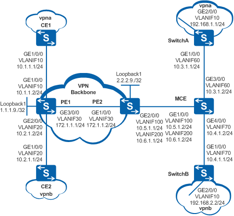
As shown in Figure 1, the networking requirements are as follows:
- CE1 and CE2 connect to the headquarters. CE1 belongs to vpna, and CE2 belongs to vpnb.
- The MCE connects to vpna and vpnb of the branch through SwitchA and SwitchB.
Users in the same VPN need to communicate with each other, whereas users in different VPNs must be isolated.
Configuration Roadmap
The configuration roadmap is as follows:
- Configure OSPF between PEs so that they can communicate and configure MP-IBGP to exchange VPN routing information.
- Configure basic MPLS capabilities and MPLS LDP on the PEs to establish LDP LSPs.
- Create VPN instances vpna and vpnb on the MCE and PEs to isolate services.
- Establish EBGP peer relationships between PE1 and its connected CEs, and import BGP routes to the VPN routing table of PE1.
- Configure routing between the MCE and VPN sites and between the MCE and PE2.
Procedure
- Configure VLANs on interfaces and assign IP addresses to
the VLANIF interfaces and loopback interfaces according to Figure 1.
# Configure PE1. The configurations on PE2, CE1, CE2, MCE, SwitchA and SwitchB are similar to the configuration on PE1 and are not mentioned here.
<HUAWEI> system-view
[HUAWEI] sysname PE1
[PE1] interface loopback 1
[PE1-LoopBack1] ip address 1.1.1.9 32
[PE1-LoopBack1] quit
[PE1] vlan batch 30
[PE1] interface gigabitethernet 3/0/0
[PE1-GigabitEthernet3/0/0] port link-type trunk
[PE1-GigabitEthernet3/0/0] port trunk allow-pass vlan 30
[PE1-GigabitEthernet3/0/0] quit
[PE1] interface vlanif 30
[PE1-Vlanif30] ip address 172.1.1.1 24
[PE1-Vlanif30] quit
- Configure OSPF on PEs of the backbone network.
# Configure PE1.
[PE1] ospf
[PE1-ospf-1] area 0
[PE1-ospf-1-area-0.0.0.0] network 1.1.1.9 0.0.0.0
[PE1-ospf-1-area-0.0.0.0] network 172.1.1.0 0.0.0.255
[PE1-ospf-1-area-0.0.0.0] quit
[PE1-ospf-1] quit
# Configure PE2.
[PE2] ospf
[PE2-ospf-1] area 0
[PE2-ospf-1-area-0.0.0.0] network 2.2.2.9 0.0.0.0
[PE2-ospf-1-area-0.0.0.0] network 172.1.1.0 0.0.0.255
[PE2-ospf-1-area-0.0.0.0] quit
[PE2-ospf-1] quit
After the configuration is complete, PEs can obtain Loopback1 address of each other.
The information displayed on PE2 is used as an example.
[PE2] display ip routing-table Route Flags: R - relay, D - download to fib, T - to vpn-instance ------------------------------------------------------------------------------ Routing Tables: Public Destinations : 10 Routes : 10 Destination/Mask Proto Pre Cost Flags NextHop Interface 1.1.1.9/32 OSPF 10 1 D 172.1.1.1 Vlanif30 2.2.2.9/32 Direct 0 0 D 127.0.0.1 LoopBack1 10.3.1.0/24 Direct 0 0 D 10.3.1.3 Vlanif60 10.3.1.3/32 Direct 0 0 D 127.0.0.1 Vlanif60 10.4.1.0/24 Direct 0 0 D 10.4.1.3 Vlanif70 10.4.1.3/32 Direct 0 0 D 127.0.0.1 Vlanif70 127.0.0.0/8 Direct 0 0 D 127.0.0.1 InLoopBack0 127.0.0.1/32 Direct 0 0 D 127.0.0.1 InLoopBack0 172.1.1.0/24 Direct 0 0 D 172.1.1.2 Vlanif30 172.1.1.2/32 Direct 0 0 D 127.0.0.1 Vlanif30 - Configure basic MPLS capabilities and MPLS LDP on the PEs
to establish LDP LSPs.
# Configure PE1. The configuration on PE2 is similar to the configuration on PE1 and is not mentioned here.
[PE1] mpls lsr-id 1.1.1.9
[PE1] mpls
[PE1-mpls] quit
[PE1] mpls ldp
[PE1-mpls-ldp] quit
[PE1] interface vlanif 30
[PE1-Vlanif30] mpls
[PE1-Vlanif30] mpls ldp
[PE1-Vlanif30] quit
After the configuration is complete, run the display mpls ldp session command on the PEs. The command output shows that the MPLS LDP session between the PEs is in Operational state.
The information displayed on PE2 is used as an example.
[PE2] display mpls ldp session LDP Session(s) in Public Network Codes: LAM(Label Advertisement Mode), SsnAge Unit(DDDD:HH:MM) A '*' before a session means the session is being deleted. ------------------------------------------------------------------------------ PeerID Status LAM SsnRole SsnAge KASent/Rcv ------------------------------------------------------------------------------ 1.1.1.9:0 Operational DU Active 0000:00:04 17/17 ------------------------------------------------------------------------------ TOTAL: 1 session(s) Found. - Configure VPN instances on the PEs. On PE1, bind the interfaces
connected to CE1 and CE2 to the VPN instances. On PE2, bind the interface
connected to the MCE to the VPN instances.
# Configure PE1.
[PE1] vlan batch 10 20
[PE1] interface gigabitethernet 1/0/0
[PE1-GigabitEthernet1/0/0] port link-type trunk
[PE1-GigabitEthernet1/0/0] port trunk allow-pass vlan 10
[PE1-GigabitEthernet1/0/0] quit
[PE1] interface gigabitethernet 2/0/0
[PE1-GigabitEthernet2/0/0] port link-type trunk
[PE1-GigabitEthernet2/0/0] port trunk allow-pass vlan 20
[PE1-GigabitEthernet2/0/0] quit
[PE1] ip vpn-instance vpna
[PE1-vpn-instance-vpna] ipv4-family
[PE1-vpn-instance-vpna-af-ipv4] route-distinguisher 100:1   //Set the RD to 100:1.
[PE1-vpn-instance-vpna-af-ipv4] vpn-target 111:1 both       //Add the RT value 100:1 to routes exported from the VPN instance vpna to MP-BGP. Only the routes with the RT value 100:1 can be imported to vpna.
[PE1-vpn-instance-vpna-af-ipv4] quit
[PE1-vpn-instance-vpna] quit
[PE1] ip vpn-instance vpnb
[PE1-vpn-instance-vpnb] ipv4-family
[PE1-vpn-instance-vpnb-af-ipv4] route-distinguisher 100:2
[PE1-vpn-instance-vpnb-af-ipv4] vpn-target 222:2 both
[PE1-vpn-instance-vpnb-af-ipv4] quit
[PE1-vpn-instance-vpnb] quit
[PE1] interface vlanif 10
[PE1-Vlanif10] ip binding vpn-instance vpna   //Bind the interface to vpna.
[PE1-Vlanif10] ip address 10.1.1.2 24
[PE1-Vlanif10] quit
[PE1] interface vlanif 20
[PE1-Vlanif20] ip binding vpn-instance vpnb
[PE1-Vlanif20] ip address 10.2.1.2 24
[PE1-Vlanif20] quit
# Configure PE2.
[PE2] vlan batch 60 70
[PE2] interface gigabitethernet 2/0/0
[PE2-GigabitEthernet2/0/0] port link-type trunk
[PE2-GigabitEthernet2/0/0] port trunk allow-pass vlan 60 70
[PE2-GigabitEthernet2/0/0] quit
[PE2] ip vpn-instance vpna
[PE2-vpn-instance-vpna] ipv4-family
[PE2-vpn-instance-vpna-af-ipv4] route-distinguisher 200:1
[PE2-vpn-instance-vpna-af-ipv4] vpn-target 111:1 both
[PE2-vpn-instance-vpna-af-ipv4] quit
[PE2-vpn-instance-vpna] quit
[PE2] ip vpn-instance vpnb
[PE2-vpn-instance-vpnb] ipv4-family
[PE2-vpn-instance-vpnb-af-ipv4] route-distinguisher 200:2
[PE2-vpn-instance-vpnb-af-ipv4] vpn-target 222:2 both
[PE2-vpn-instance-vpnb-af-ipv4] quit
[PE2-vpn-instance-vpnb] quit
[PE2] interface vlanif 60
[PE2-Vlanif60] ip binding vpn-instance vpna
[PE2-Vlanif60] ip address 10.3.1.3 24
[PE2-Vlanif60] quit
[PE2] interface vlanif 70
[PE2-Vlanif70] ip binding vpn-instance vpnb
[PE2-Vlanif70] ip address 10.4.1.3 24
[PE2-Vlanif70] quit
- Configure VPN instances on the MCE and bind the interfaces
connected to SwitchA and SwitchB to the VPN instances.
<HUAWEI> system-view
[HUAWEI] sysname MCE
[MCE] vlan batch 60 70
[MCE] interface gigabitethernet 1/0/0
[MCE-GigabitEthernet1/0/0] port link-type trunk
[MCE-GigabitEthernet1/0/0] port trunk allow-pass vlan 60 70
[MCE-GigabitEthernet1/0/0] quit
[MCE] interface gigabitethernet 3/0/0
[MCE-GigabitEthernet3/0/0] port link-type trunk
[MCE-GigabitEthernet3/0/0] port trunk allow-pass vlan 60
[MCE-GigabitEthernet3/0/0] quit
[MCE] interface gigabitethernet 4/0/0
[MCE-GigabitEthernet4/0/0] port link-type trunk
[MCE-GigabitEthernet4/0/0] port trunk allow-pass vlan 70
[MCE-GigabitEthernet4/0/0] quit
[MCE] ip vpn-instance vpna
[MCE-vpn-instance-vpna] ipv4-family
[MCE-vpn-instance-vpna-af-ipv4] route-distinguisher 100:1
[MCE-vpn-instance-vpna-af-ipv4] quit
[MCE-vpn-instance-vpna] quit
[MCE] ip vpn-instance vpnb
[MCE-vpn-instance-vpnb] ipv4-family
[MCE-vpn-instance-vpnb-af-ipv4] route-distinguisher 100:2
[MCE-vpn-instance-vpnb-af-ipv4] quit
[MCE-vpn-instance-vpnb] quit
[MCE] interface vlanif 60
[MCE-Vlanif60] ip binding vpn-instance vpna
[MCE-Vlanif60] ip address 10.3.1.2 24
[MCE-Vlanif60] quit
[MCE] interface vlanif 70
[MCE-Vlanif70] ip binding vpn-instance vpnb
[MCE-Vlanif70] ip address 10.4.1.2 24
[MCE-Vlanif70] quit
- Establish an MP-IBGP peer relationship between PEs. Establish
an EBGP peer relationship between PE1 and CE1, and between PE1 and
CE2.
# Configure CE1. The configuration on CE2 is similar to the configuration on CE1 and is not mentioned here.
[CE1] bgp 65410
[CE1-bgp] peer 10.1.1.2 as-number 100   //Establish an EBGP peer relationship between PE1 and CE1 and import VPN routes.
[CE1-bgp] import-route direct
[CE1-bgp] quit
# Configure PE1. The configuration on PE2 is similar to the configuration on PE1 and is not mentioned here.
[PE1] bgp 100
[PE1-bgp] ipv4-family vpn-instance vpna
[PE1-bgp-vpna] peer 10.1.1.1 as-number 65410
[PE1-bgp-vpna] import-route direct
[PE1-bgp-vpna] quit
[PE1-bgp] ipv4-family vpn-instance vpnb
[PE1-bgp-vpnb] peer 10.2.1.1 as-number 65420
[PE1-bgp-vpnb] import-route direct
[PE1-bgp-vpnb] quit
[PE1-bgp] quit
Set up an MP-IBGP peer relationship between the PE devices.
# Configure PE1. The configuration on PE2 is similar to the configuration on PE1 and is not mentioned here.
[PE1] bgp 100
[PE1-bgp] peer 2.2.2.9 as-number 100
[PE1-bgp] peer 2.2.2.9 connect-interface loopback 1
[PE1-bgp] ipv4-family vpnv4
[PE1-bgp-af-vpnv4] peer 2.2.2.9 enable
[PE1-bgp-af-vpnv4] quit
[PE1-bgp] quit
After the configuration is complete, run the display bgp vpnv4 all peer command on PE1. The command output shows that PE1 has established an IBGP peer relationship with PE2 and EBGP peer relationships with CE1 and CE2. The peer relationships are in Established state.
[PE1] display bgp vpnv4 all peer

 BGP local router ID : 1.1.1.9
 Local AS number : 100
 Total number of peers : 3                 Peers in established state : 3

  Peer            V    AS  MsgRcvd  MsgSent  OutQ  Up/Down       State PrefRcv

  2.2.2.9         4   100      288      287     0 01:19:16     Established       6

  Peer of IPv4-family for vpn instance :

 VPN-Instance vpna, Router ID 1.1.1.9:
  10.1.1.1        4  65410       9       11     0 00:01:38     Established       2

 VPN-Instance vpnb, Router ID 1.1.1.9:
  10.2.1.1        4  65420       9       12     0 00:04:09     Established       2
- Configure routing between the MCE and VPN sites.
The MCE directly connects to vpna, which uses no routing protocol. Configure static routes to implement communication between the MCE and vpna.
# Configure SwitchA.
Assign IP address 192.168.1.1/24 to the interface connected to vpna. The configuration details are not mentioned here.
<HUAWEI> system-view
[HUAWEI] sysname SwitchA
[SwitchA] vlan batch 60
[SwitchA] interface gigabitethernet 1/0/0
[SwitchA-GigabitEthernet1/0/0] port link-type trunk
[SwitchA-GigabitEthernet1/0/0] port trunk allow-pass vlan 60
[SwitchA-GigabitEthernet1/0/0] quit
[SwitchA] interface vlanif 60
[SwitchA-Vlanif60] ip address 10.3.1.1 24
[SwitchA-Vlanif60] quit
[SwitchA] ip route-static 0.0.0.0 0.0.0.0 10.3.1.2   //Create a default route destined to the MCE for SwitchA.
# Configure the MCE.
[MCE] ip route-static vpn-instance vpna 192.168.1.0 24 10.3.1.1 //Create a VPN route destined to SwitchA for the VPN instance vpna.- # Check the routes of vpna on the MCE.
[MCE] display ip routing-table vpn-instance vpna
Route Flags: R - relay, D - download to fib, T - to vpn-instance
------------------------------------------------------------------------------
Routing Tables: vpna
         Destinations : 3        Routes : 3

Destination/Mask    Proto   Pre  Cost      Flags NextHop         Interface

       10.3.1.0/24  Direct  0    0           D   10.3.1.2        Vlanif60
       10.3.1.2/32  Direct  0    0           D   127.0.0.1       Vlanif60
    192.168.1.0/24  Static  60   0          RD   10.3.1.1        Vlanif60
The preceding information shows that the MCE has a static route to vpna.
The RIP protocol runs in vpnb. Configure RIP process 200 on the MCE and bind it to vpnb so that routes learned by RIP are added to the routing table of vpnb.
- # Configure the MCE.
[MCE] rip 200 vpn-instance vpnb
[MCE-rip-200] version 2
[MCE-rip-200] network 10.0.0.0
[MCE-rip-200] import-route ospf 200   //Import OSPF routes so that SwitchB can learn routes to the MCE.
[MCE-rip-200] quit
# Configure SwitchB.
Assign IP address 192.168.2.1/24 to the interface connected to vpnb. The configuration is not mentioned here.
<HUAWEI> system-view
[HUAWEI] sysname SwitchB
[SwitchB] vlan batch 70
[SwitchB] interface gigabitethernet 1/0/0
[SwitchB-GigabitEthernet1/0/0] port link-type trunk
[SwitchB-GigabitEthernet1/0/0] port trunk allow-pass vlan 70
[SwitchB-GigabitEthernet1/0/0] quit
[SwitchB] interface vlanif 70
[SwitchB-Vlanif70] ip address 10.4.1.1 24
[SwitchB-Vlanif70] quit
[SwitchB] rip 200
[SwitchB-rip-200] version 2
[SwitchB-rip-200] network 10.0.0.0
[SwitchB-rip-200] network 192.168.2.0
[SwitchB-rip-200] quit
- # Check the routes of vpnb on the MCE.
[MCE] display ip routing-table vpn-instance vpnb
Route Flags: R - relay, D - download to fib, T - to vpn-instance
------------------------------------------------------------------------------
Routing Tables: vpnb
         Destinations : 3        Routes : 3

Destination/Mask    Proto   Pre  Cost      Flags NextHop         Interface

       10.4.1.0/24  Direct  0    0           D   10.4.1.2        Vlanif70
       10.4.1.2/32  Direct  0    0           D   127.0.0.1       Vlanif70
    192.168.2.0/24  RIP     100  1           D   10.4.1.1        Vlanif70
The preceding information shows that the MCE has learned the route to vpnb using RIP. The route to vpnb and the route to vpna (192.168.1.0) are maintained in different VPN routing tables so that users in the two VPNs are isolated from each other.
- Configure OSPF multi-instance between the MCE and PE2.
# Configure PE2. To configure OSPF multi-instance between the MCE and PE2, complete the following tasks on PE2:
- In the OSPF view, import BGP routes and advertise VPN routes of PE1 to the MCE.
- In the BGP view, import routes of the OSPF processes and advertise the VPN routes of the MCE to PE1.
[PE2] ospf 100 vpn-instance vpna
[PE2-ospf-100] import-route bgp   //Import BGP routes to OSPF 100 in vpna between the PE and MCE, so that the MCE learns routes to CE1.
[PE2-ospf-100] area 0
[PE2-ospf-100-area-0.0.0.0] network 10.3.1.0 0.0.0.255
[PE2-ospf-100-area-0.0.0.0] quit
[PE2-ospf-100] quit
[PE2] ospf 200 vpn-instance vpnb
[PE2-ospf-200] import-route bgp   //Import BGP routes to OSPF 200 in vpnb between the PE and MCE, so that the MCE learns routes to CE2.
[PE2-ospf-200] area 0
[PE2-ospf-200-area-0.0.0.0] network 10.4.1.0 0.0.0.255
[PE2-ospf-200-area-0.0.0.0] quit
[PE2-ospf-200] quit
[PE2] bgp 100
[PE2-bgp] ipv4-family vpn-instance vpna
[PE2-bgp-vpna] import-route ospf 100   //Import OSPF 100 to BGP so that PE2 adds the VPNv4 prefix to routes and uses MP-IBGP to advertise routes to PE1.
[PE2-bgp-vpna] quit
[PE2-bgp] ipv4-family vpn-instance vpnb
[PE2-bgp-vpnb] import-route ospf 200   //Import OSPF 200 to BGP so that PE2 adds the VPNv4 prefix to routes and uses MP-IBGP to advertise routes to PE1.
[PE2-bgp-vpnb] quit
# Configure the MCE. Import VPN routes to the OSPF processes.
[MCE] ospf 100 vpn-instance vpna           //Configure dynamic OSPF routes for the VPN instance vpna.
[MCE-ospf-100] import-route static              //Import static private routes of SwitchA to the MCE.
[MCE-ospf-100] vpn-instance-capability simple   //Disable loop detection for OSPF VPN, so that the MCE can learn routes re-advertised from PE2.
[MCE-ospf-100] area 0
[MCE-ospf-100-area-0.0.0.0] network 10.3.1.0 0.0.0.255
[MCE-ospf-100-area-0.0.0.0] quit
[MCE-ospf-100] quit
[MCE] ospf 200 vpn-instance vpnb
[MCE-ospf-200] import-route rip 200
[MCE-ospf-200] vpn-instance-capability simple
[MCE-ospf-200] area 0
[MCE-ospf-200-area-0.0.0.0] network 10.4.1.0 0.0.0.255
[MCE-ospf-200-area-0.0.0.0] quit
[MCE-ospf-200] quit
- Verify the configuration.
After the configuration is complete, run the display ip routing-table vpn-instance command on the MCE to view the routes to the remote CEs.
The VPN instance vpna is used as an example.
[MCE] display ip routing-table vpn-instance vpna
Route Flags: R - relay, D - download to fib, T - to vpn-instance
------------------------------------------------------------------------------
Routing Tables: vpna
         Destinations : 4        Routes : 4

Destination/Mask    Proto   Pre  Cost      Flags NextHop         Interface

       10.1.1.0/24  O_ASE   150  1           D   10.3.1.3        Vlanif60
       10.3.1.0/24  Direct  0    0           D   10.3.1.2        Vlanif60
       10.3.1.2/32  Direct  0    0           D   127.0.0.1       Vlanif60
    192.168.1.0/24  Static  60   0          RD   10.3.1.1        Vlanif60
Run the display ip routing-table vpn-instance command on the PEs to view the routes to the remote CEs.
The VPN instance vpna on PE1 is used as an example.
[PE1] display ip routing-table vpn-instance vpna
Route Flags: R - relay, D - download to fib, T - to vpn-instance
------------------------------------------------------------------------------
Routing Tables: vpna
         Destinations : 4        Routes : 4

Destination/Mask    Proto   Pre  Cost      Flags NextHop         Interface

       10.1.1.0/24  Direct  0    0           D   10.1.1.2        Vlanif10
       10.1.1.2/32  Direct  0    0           D   127.0.0.1       Vlanif10
       10.3.1.0/24  IBGP    255  0          RD   2.2.2.9         Vlanif30
    192.168.1.0/24  IBGP    255  2          RD   2.2.2.9         Vlanif30
CE1 and SwitchA can communicate with each other. CE2 and SwitchB can communicate with each other.
The information displayed on CE1 is used as an example.
[CE1] ping 10.3.1.1
  PING 10.3.1.1: 56 data bytes, press CTRL_C to break
    Reply from 10.3.1.1: bytes=56 Sequence=1 ttl=252 time=3 ms
    Reply from 10.3.1.1: bytes=56 Sequence=2 ttl=252 time=3 ms
    Reply from 10.3.1.1: bytes=56 Sequence=3 ttl=252 time=3 ms
    Reply from 10.3.1.1: bytes=56 Sequence=4 ttl=252 time=3 ms
    Reply from 10.3.1.1: bytes=56 Sequence=5 ttl=252 time=11 ms

  --- 10.3.1.1 ping statistics ---
    5 packet(s) transmitted
    5 packet(s) received
    0.00% packet loss
    round-trip min/avg/max = 3/4/11 ms
CE1 cannot ping CE2 or SwitchB. SwitchA cannot ping CE2 or SwitchB.
The ping from CE1 to SwitchB is used as an example.
[CE1] ping 10.4.1.1
  PING 10.4.1.1: 56  data bytes, press CTRL_C to break
    Request time out
    Request time out
    Request time out
    Request time out
    Request time out

  --- 10.4.1.1 ping statistics ---
    5 packet(s) transmitted
    0 packet(s) received
    100.00% packet loss
Configuration Files
Configuration file of CE1
#
sysname CE1
#
vlan batch 10
#
interface Vlanif10
 ip address 10.1.1.1 255.255.255.0
#
interface GigabitEthernet1/0/0
 port link-type trunk
 port trunk allow-pass vlan 10
#
bgp 65410
 peer 10.1.1.2 as-number 100
 #
 ipv4-family unicast
  undo synchronization
  import-route direct
  peer 10.1.1.2 enable
#
return
Configuration file of CE2
#
sysname CE2
#
vlan batch 20
#
interface Vlanif20
 ip address 10.2.1.1 255.255.255.0
#
interface GigabitEthernet1/0/0
 port link-type trunk
 port trunk allow-pass vlan 20
#
bgp 65420
 peer 10.2.1.2 as-number 100
 #
 ipv4-family unicast
  undo synchronization
  import-route direct
  peer 10.2.1.2 enable
#
return
Configuration file of PE1
#
sysname PE1
#
vlan batch 10 20 30
#
ip vpn-instance vpna
 ipv4-family
  route-distinguisher 100:1
  vpn-target 111:1 export-extcommunity
  vpn-target 111:1 import-extcommunity
#
ip vpn-instance vpnb
 ipv4-family
  route-distinguisher 100:2
  vpn-target 222:2 export-extcommunity
  vpn-target 222:2 import-extcommunity
#
mpls lsr-id 1.1.1.9
mpls
#
mpls ldp
#
interface Vlanif10
 ip binding vpn-instance vpna
 ip address 10.1.1.2 255.255.255.0
#
interface Vlanif20
 ip binding vpn-instance vpnb
 ip address 10.2.1.2 255.255.255.0
#
interface Vlanif30
 ip address 172.1.1.1 255.255.255.0
 mpls
 mpls ldp
#
interface GigabitEthernet1/0/0
 port link-type trunk
 port trunk allow-pass vlan 10
#
interface GigabitEthernet2/0/0
 port link-type trunk
 port trunk allow-pass vlan 20
#
interface GigabitEthernet3/0/0
 port link-type trunk
 port trunk allow-pass vlan 30
#
interface LoopBack1
 ip address 1.1.1.9 255.255.255.255
#
bgp 100
 peer 2.2.2.9 as-number 100
 peer 2.2.2.9 connect-interface LoopBack1
 #
 ipv4-family unicast
  undo synchronization
  peer 2.2.2.9 enable
 #
 ipv4-family vpnv4
  policy vpn-target
  peer 2.2.2.9 enable
 #
 ipv4-family vpn-instance vpna
  import-route direct
  peer 10.1.1.1 as-number 65410
 #
 ipv4-family vpn-instance vpnb
  import-route direct
  peer 10.2.1.1 as-number 65420
#
ospf 1
 area 0.0.0.0
  network 1.1.1.9 0.0.0.0
  network 172.1.1.0 0.0.0.255
#
return
Configuration file of PE2
#
sysname PE2
#
vlan batch 30 60 70
#
ip vpn-instance vpna
 ipv4-family
  route-distinguisher 200:1
  vpn-target 111:1 export-extcommunity
  vpn-target 111:1 import-extcommunity
#
ip vpn-instance vpnb
 ipv4-family
  route-distinguisher 200:2
  vpn-target 222:2 export-extcommunity
  vpn-target 222:2 import-extcommunity
#
mpls lsr-id 2.2.2.9
mpls
#
mpls ldp
#
interface Vlanif30
 ip address 172.1.1.2 255.255.255.0
 mpls
 mpls ldp
#
interface Vlanif60
 ip binding vpn-instance vpna
 ip address 10.3.1.3 255.255.255.0
#
interface Vlanif70
 ip binding vpn-instance vpnb
 ip address 10.4.1.3 255.255.255.0
#
interface LoopBack1
 ip address 2.2.2.9 255.255.255.255
#
interface GigabitEthernet1/0/0
 port link-type trunk
 port trunk allow-pass vlan 30
#
interface GigabitEthernet2/0/0
 port link-type trunk
 port trunk allow-pass vlan 60 70
#
bgp 100
 peer 1.1.1.9 as-number 100
 peer 1.1.1.9 connect-interface LoopBack1
 #
 ipv4-family unicast
  undo synchronization
  peer 1.1.1.9 enable
 #
 ipv4-family vpnv4
  policy vpn-target
  peer 1.1.1.9 enable
 #
 ipv4-family vpn-instance vpna
  import-route ospf 100
 #
 ipv4-family vpn-instance vpnb
  import-route ospf 200
#
ospf 1
 area 0.0.0.0
  network 2.2.2.9 0.0.0.0
  network 172.1.1.0 0.0.0.255
#
ospf 100 vpn-instance vpna
 import-route bgp
 area 0.0.0.0
  network 10.3.1.0 0.0.0.255
#
ospf 200 vpn-instance vpnb
 import-route bgp
 area 0.0.0.0
  network 10.4.1.0 0.0.0.255
#
return
Configuration file of the MCE
#
sysname MCE
#
vlan batch 60 70
#
ip vpn-instance vpna
 ipv4-family
  route-distinguisher 100:1
#
ip vpn-instance vpnb
 ipv4-family
  route-distinguisher 100:2
#
interface Vlanif60
 ip binding vpn-instance vpna
 ip address 10.3.1.2 255.255.255.0
#
interface Vlanif70
 ip binding vpn-instance vpnb
 ip address 10.4.1.2 255.255.255.0
#
interface GigabitEthernet1/0/0
 port link-type trunk
 port trunk allow-pass vlan 60 70
#
interface GigabitEthernet3/0/0
 port link-type trunk
 port trunk allow-pass vlan 60
#
interface GigabitEthernet4/0/0
 port link-type trunk
 port trunk allow-pass vlan 70
#
ospf 100 vpn-instance vpna
 import-route static
 vpn-instance-capability simple
 area 0.0.0.0
  network 10.3.1.0 0.0.0.255
#
ospf 200 vpn-instance vpnb
 import-route rip 200
 vpn-instance-capability simple
 area 0.0.0.0
  network 10.4.1.0 0.0.0.255
#
rip 200 vpn-instance vpnb
 version 2
 network 10.0.0.0
 import-route ospf 200
#
ip route-static vpn-instance vpna 192.168.1.0 255.255.255.0 10.3.1.1
#
return
Configuration file of SwitchA
#
sysname SwitchA
#
vlan batch 60
#
interface Vlanif60
 ip address 10.3.1.1 255.255.255.0
#
interface GigabitEthernet1/0/0
 port link-type trunk
 port trunk allow-pass vlan 60
#
ip route-static 0.0.0.0 0.0.0.0 10.3.1.2
#
return
Configuration file of SwitchB
#
sysname SwitchB
#
vlan batch 70
#
interface Vlanif70
 ip address 10.4.1.1 255.255.255.0
#
interface GigabitEthernet1/0/0
 port link-type trunk
 port trunk allow-pass vlan 70
#
rip 200
 version 2
 network 10.0.0.0
 network 192.168.2.0
#
return