Basic Concepts of MPLS TE
LSP
On a label switched path (LSP), traffic forwarding is determined by the labels added to packets by the ingress node of the LSP. An LSP can be considered as a tunnel because traffic is transparently transmitted on intermediate nodes along the LSP.
MPLS TE Tunnel
- Tunnel interface: a point-to-point virtual interface used to encapsulate packets. Similar to a loopback interface, a tunnel interface is a logical interface.
- Tunnel ID: a decimal number that uniquely identifies an MPLS TE tunnel to facilitate tunnel planning and management.
- LSP ID: a decimal number that uniquely identifies an LSP to facilitate LSP planning and management.
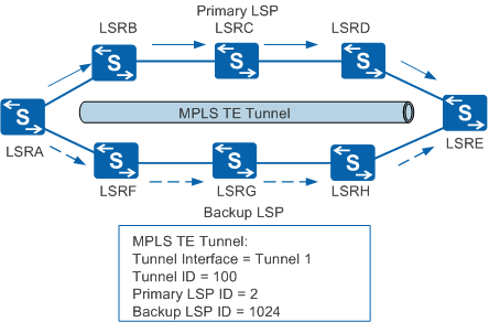
Figure 1 illustrates the preceding terms. Two LSPs are available on the network. The path LSRA->LSRB->LSRC->LSRD->LSRE is the primary LSP with an LSP ID of 2. The path LSRA->LSRF->LSRG->LSRH->LSRE is the backup LSP with an LSP ID of 1024. The two LSPs form an MPLS TE tunnel with a tunnel ID of 100, and the tunnel interface is Tunnel1.
Link Attributes
Total link bandwidth
Bandwidth of a physical link.
Maximum reservable bandwidth
Maximum bandwidth that a link can reserve for an MPLS TE tunnel. The maximum reservable bandwidth must be lower than or equal to the total link bandwidth.
TE metric
Cost of a TE link. TE metrics are used to control MPLS TE path calculation, making path calculation more independent of IGP routing. By default, IGP metrics are used as TE metrics.
SRLG
Shared risk link group (SRLG), a group of links that share a physical resource, such as an optical fiber. Links in an SRLG have the same risk. If one link fails, other links in the SRLG also fail.
The SRLG attribute is used in CR-LSP hot standby and TE fast reroute (FRR) to enhance TE tunnel reliability. For details about SRLG, see SRLG.
-
A 32-bit vector that identifies link attributes, also called a link color. Each bit can be set to 0 or 1 by the network administrator. A link administrative group identifies an attribute, such as the link bandwidth or performance. A link administrative group can also be used for link management. For example, it can identify that an MPLS TE tunnel passes through a link or that a link is transmitting multicast services. The administrative group attribute must be used with the affinity attribute to control path selection.
Tunnel Attributes
An MPLS TE tunnel is composed of several constraint-based routed label switched paths (CR-LSPs). The constraints for LSP setup are tunnel attributes.
Bandwidth constraints
Bandwidth constraint is mainly the tunnel bandwidth.
Path constraints
Path constraints include explicit path, priority and preemption, route pinning, affinity attribute, and hop limit.
Constraint-based routing (CR) is a mechanism to create and manage these constraints, which are described in the following:
Tunnel bandwidth
The bandwidth of a tunnel must be planned according to requirements of the services to be transmitted over the tunnel. The planned bandwidth is reserved on the links along the tunnel to provide bandwidth guarantee.
Explicit path
An explicit path is a CR-LSP manually set up by specifying the nodes to pass or avoid. Explicit paths are classified into the following types:
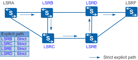
Strict explicit path
On a strict explicit path, all the nodes are manually specified and two consecutive hops must be directly connected. A strict explicit path precisely controls the path of an LSP.
As shown in Figure 2, LSRA is the ingress node, and LSRF is the egress node. An LSP from LSRA to LSRF is set up over a strict explicit path. LSRB Strict indicates that this LSP must pass through LSRB, which is directly connected to LSRA. LSRC Strict indicates that this LSP must pass through LSRC, which is directly connected to LSRB. The rest may be deduced by analogy. In this way, the path that the LSP passes through is precisely controlled.
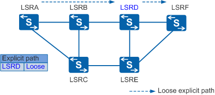
Loose explicit path
A loose explicit path passes through the specified nodes but allows intermediate nodes between the specified nodes.
As shown in Figure 3, an LSP is set up over a loose explicit path from LSRA to LSRF. LSRD Loose indicates that this LSP must pass through LSRD, but LSRD may not be directly connected to LSRA.
Priority and preemption
Priority and preemption determine resources allocated to MPLS TE tunnels based on the importance of services to be transmitted on the tunnels.
Setup priorities and holding priorities of tunnels determine whether a new tunnel can preempt the resources of existing tunnels. If the setup priority of a new CR-LSP is higher than the holding priority of an existing CR-LSP, the new CR-LSP can occupy resources of the existing CR-LSP. The priority value ranges from 0 to 7, among which the value 0 indicates the highest priority, and the value 7 indicates the lowest priority. The setup priority of a tunnel must be lower than or equal to the holding priority of the tunnel.
If no path can provide the required bandwidth for a new CR-LSP, an existing CR-LSP is torn down and its bandwidth is assigned to the new CR-LSP. This is the preemption process. The following preemption modes are supported:- Hard preemption: A high-priority CR-LSP can directly preempt resources assigned to a low-priority CR-LSP. As a result, some traffic is dropped on the low-priority CR-LSP.
- Soft preemption: The make-before-break mechanism applies to resource preemption. A high-priority CR-LSP preempts bandwidth assigned to a lower-priority CR-LSP only after traffic over the low-priority CR-LSP switches to a new CR-LSP.
The priority and preemption attributes determine resource preemption among tunnels. If multiple CR-LSPs need to be set up, CR-LSPs with higher setup priorities can be set up by preempting resources. If resources (such as bandwidth) are insufficient, a CR-LSP with a higher setup priority can preempt resources of an established CR-LSP with a lower holding priority.
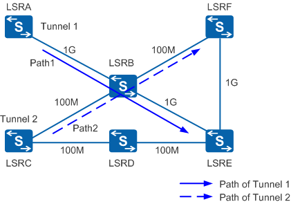
As shown in Figure 4, links on the network have different bandwidth values but the same metric value. There are two TE tunnels on the network:- Tunnel 1: established over Path 1. Its bandwidth is 100 Mbit/s, and its setup and holding priority values are 0.
- Tunnel 2: established over Path 2. Its bandwidth is 100 Mbit/s, and its setup and holding priority values are 7.
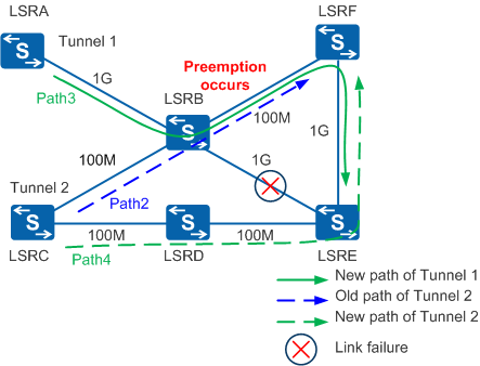
When the link between LSRB and LSRE fails, LSRA calculates a new path, Path 3 (LSRA->LSRB->LSRF->LSRE), for Tunnel 1. The bandwidth of the link between LSRB and LSRF is insufficient for tunnels Tunnel 1 and Tunnel 2. As a result, preemption is triggered, as shown in Figure 5.A new path is set up for Tunnel 1 as follows:- After MPLS TE path calculation is complete, Path messages are transmitted along the path LSRA->LSRB->LSRF->LSRE, and Resv messages are transmitted along the path LSRE->LSRF->LSRB->LSRA.
- When a Resv message is sent from LSRF to LSRB, LSRB needs to reserve bandwidth for the new path but finds that bandwidth is insufficient. Then preemption occurs. LSRB processes the low-priority path differently in hard and soft preemption modes:
- In hard preemption mode: Tunnel 1 has a higher priority than Tunnel 2, so LSRB tears down Path 2 of Tunnel 2. In addition, LSRB sends a PathTear message to request LSRF to delete the path information, and sends a ResvTear to request LSRC to delete the reservation state. If traffic is being transmitted on Tunnel 2, some traffic is dropped.
- In soft preemption mode: LSRB sends a ResvTear message to LSRC. A new path, Path 4, is set up while Path 2 is not torn down. After traffic on Path 2 is switched to Path 4, LSRB and LSRC tear down Path 2 on Tunnel 2.
-
Changes in the network topology or some tunnel attributes may require a CR-LSP to be reestablished. Reestablishing a CR-LSP may cause the following problems:
- The new CR-LSP is set up along a different path than the original one, making network maintenance inconvenient.
- Some traffic is dropped when traffic is switched from the original CR-LSP to the new one.
Path locking can prevent a CR-LSP from changing its path when routes change. This feature ensures continuity of service traffic and improves service reliability.
-
The affinity attribute is a 32-bit vector that specifies the links required for a TE tunnel. This attribute is configured on the ingress node of a tunnel and must be used with the link administrative group attribute.
After the affinity attribute is configured for a tunnel, a label switching router (LSR) compares the affinity attribute with the administrative group attribute of a link to determine whether to select or avoid the link during MPLS TE path calculation. A 32-bit mask identifies the bits to be compared in the affinity and administrative group attributes. An LSR performs an AND operation on the affinity and administrative group attributes with the mask and compares the results of the AND operations. If the two results are the same, the LSR selects the link. If the two results are different, the LSR avoids the link. The rules for comparing the affinity and administrative group attributes are as follows:Among the bits mapping the 1 bit in the mask, at least one administrative group bit and the corresponding affinity bit must be 1. The administrative group bits corresponding to the 0 bits in the affinity attribute must also be 0.
For example, if the affinity attribute is 0x0000FFFF of a tunnel and the mask is 0xFFFFFFFF, the administrative group attribute of an available link must have all 0s in its leftmost 16 bits and at least one 1 bit in its rightmost 16 bits. Therefore, links with the administrative group values in the range of 0x00000001 to 0x0000FFFF can be selected for the tunnel.
An LSR does not check the administrative group bits mapping 0 bits in the mask.
For example, if the affinity attribute of a tunnel is 0xFFFFFFFF and the mask is 0xFFFF0000, the administrative group attribute of an available link must have at least one 1 bit in its leftmost 16 bits. The rightmost 16 bits of the administrative group attribute can be 0 or 1. Therefore, links with the administrative group values in the range of 0x00010000 to 0xFFFFFFFF can be selected for the tunnel.

Devices from different vendors may follow different rules to compare the administrative group and affinity attributes. When using devices from different vendors on your network, understand their implementations and ensure that they can interoperate with one another.
A network administrator can use the administrative group and affinity attributes to control path selection for tunnels.
Hop limit
Hop limit is a condition for path selection during CR-LSP setup. Similar to the administrative group and affinity attributes, hop limit controls the number of hops allowed on a CR-LSP.