Implementation
Figure 1 illustrates the MPLS TE framework.
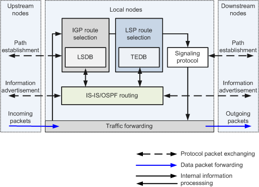
- IGP-based information advertisement for TE information collection
- Path calculation using the collected information
- Path setup through signaling packet exchange between upstream and downstream nodes
- Traffic forwarding over an established MPLS TE tunnel
Table 1 describes the four functions.
No. |
Function |
Description |
|---|---|---|
1 |
Collects network load information in addition to routing information. MPLS TE extends an IGP to advertise TE information, including the maximum link bandwidth, maximum reservable bandwidth, reserved bandwidth, and link colors. Every node collects TE information about all links in a local area and generates a traffic engineering database (TEDB). |
|
2 |
Uses the Constrained Shortest Path First (CSPF) algorithm and data in the TEDB to calculate a path that satisfies specific constraints. CSPF evolves from the Shortest Path First (SPF) algorithm. It excludes nodes and links that do not satisfy specific constraints and uses the SPF algorithm to calculate a path. |
|
3 |
Sets up a static or
dynamic CR-LSP.
|
|
4 |
Directs traffic to an MPLS TE tunnel and forwards traffic over the MPLS TE tunnel. The first three functions set up an MPLS TE tunnel, and the traffic forwarding function directs traffic arriving at a node to the MPLS-TE tunnel. |

- A static CR-LSP is manually established and does not require information advertisement or path calculation.
- A dynamic CR-LSP is set up using a signaling protocol and involves all the four functions listed in the table.
To deploy MPLS TE on a network, you must configure link and tunnel attributes. Then MPLS TE sets up tunnels automatically. After a tunnel is set up, traffic is directed to the tunnel for forwarding.