WLAN Architecture
A WLAN has a wired side and a wireless side. On the wired side, an AP connects to the Internet using Ethernet. On the wireless side, a STA communicates with an AP using 802.11 standards. The WLAN architecture on the wireless side is the centralized architecture.
The centralized architecture includes the Fit AP architecture and the agile distributed architecture.
Fit AP Architecture
In Fit AP architecture, an AC manages and controls multiple APs (Fit APs) in a centralized manner, as shown in Figure 1.
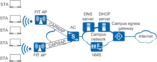
In Fit AP architecture,
APs work together with an AC to implement wireless access.
- The AC implements all security, control, and management functions. These functions include mobile user management, identity authentication, VLAN assignment, radio management, and data forwarding.
- Fit APs implement wireless radio access, including radio signal transmission and detection response, data encryption and decryption, and data transmission acknowledgment.
- The AC and APs communicate using Control and Provisioning of Wireless Access Points (CAPWAP). They can be connected across a Layer 2 or Layer 3 network.
In centralized architecture, wireless access involves the following operations:
- Fit APs establish CAPWAP tunnels with an AC. For details, see AP Online Process.
- STAs associate with a Fit AP. For details, see STA Access.
Agile Distributed Architecture
In agile distributed architecture, an AC manages and controls multiple central APs in a centralized manner, and each central AP manages and controls
RUs, as shown in Figure 2. 
A central AP cannot be cascaded with another central AP for extending the network.
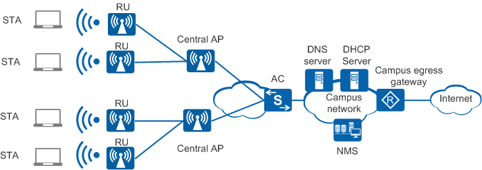
In agile distributed
architecture, RUs, central APs, and ACs work together to implement wireless access.
- The AC implements all security, control, and management functions. These functions include mobile user management, identity authentication, VLAN assignment, radio management, and data forwarding.
- The RU used as the remote radio module of the central AP is responsible for receiving and transmitting 802.11 packets of the air interface.
- The central AP (proxy of the AC) provides centralized management and coordination of RUs, including STA login, configuration delivery, and STA roaming between RUs.
- A Layer 2 or Layer 3 network can be deployed between the central AP and AC, and the RU and central AP must communicate at Layer 2.
Wireless access includes the following steps:
- Central AP going online: Central APs set up CAPWAP tunnels with an AC. For details, see AP Online Process.
- RUs going online:
- When RUs are connected to an AD9430DN-12 or AD9430DN-24, they set up CAPWAP tunnels with the central AP. For details, see RU Online Process.
- When RUs are connected to an AD9431DN-24X: In tunnel forwarding mode, the RUs set up CAPWAP tunnels with the AC; in direct forwarding mode, services are forwarded directly at Layer 2, without the CAPWAP tunnel. For details, see RU Online Process.
- STA access: STAs associate with a central AP or RU. For details, see STA Access.