Example for Configuring iPCA to Implement Hop-by-Hop Packet Loss Measurement
iPCA Overview
Packet Conservation Algorithm for Internet (iPCA) technology is used to measure IP network performance. It directly marks service packets to implement network-level and device-level packet loss measurements.
In the all-IP era, various services sensitive to packet loss, such as voice and video services, are transmitted through an IP network. To detect packet loss and find out packet loss points on the network, Huawei developed iPCA technology. Huawei iPCA has the following characteristics:
- iPCA applies to both Layer 2 and Layer 3 networks.
- iPCA directly marks service packets to obtain the packet loss ratio and number of lost packets, without increasing loads on devices.
- iPCA supports packet loss statistics collection on multipoint-to-multipoint networks.
Hop-by-hop packet loss measurement: Statistics are collected on every device on the network. If you want to locate the network node where packet loss occurs, you can use this method.
Configuration Notes
- For the applicable product models and versions of this example, see Applicable product models and versions.
- The prerequisite of network-level packet loss measurement is time synchronization between iPCA devices. Therefore, before configuring iPCA, configure NTP on the devices.
- In network-level packet loss measurement, the device can color known IP unicast packets but not MPLS packets or unknown IP unicast packets.
- Network-level packet loss measurement is based on target flows, you can specify target flows. If the packet content is modified (for example, NAT is performed on packets, packets are encapsulated in tunnels, and packet priority is changed), the device cannot precisely match the packets, so the measurement result may be inaccurate.
- In an MPLS L2VPN scenario, network-level packet loss measurement cannot be configured, including end-to-end packet loss measurement, regional network packet loss measurement, and network-level hop-by-hop packet loss measurement.
- In an MPLS L3VPN scenario, end-to-end packet loss measurement can be configured on private network interfaces of PEs, regional network packet loss measurement can be configured on the CEs, and network-level hop-by-hop packet loss measurement cannot be configured.
- End-to-end and regional network packet loss measurement support on-demand and proactive packet loss measurement. Network-level hop-by-hop packet loss measurement only supports on-demand packet loss measurement.
Networking Requirements
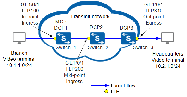
As shown in Figure 1, users in enterprise branches and headquarters encounter erratic display and delay when using the video conference service. Network-level end--to-end packet loss measurement has been deployed, and packet loss on the transit network has been detected. To find out where packets are lost in a specified network range, hop-by-hop packet loss measurement must be configured for the specified service flow.
Configuration Roadmap
Configure hop-by-hop packet loss measurement between Switch_1 and Switch_3 to locate faults on the transit network based on network segments. According to the Atomic Closed Hop (ACH) rule, divide the link between Switch_1 and Switch_3 into two ACHs: ACH1 { TLP 100, TLP 200 } and ACH2 { TLP 200, TLP 310 }.
Configure Switch_1 as the MCP to collect packet loss statistics from DCP1, DCP2, and DCP3, summarize and calculate the statistical data, and report the statistical results to user terminals or NMS.
Configure the IP FPM packet loss alarm threshold and recovery threshold on Switch_1 so that Switch_1 can send alarms to the NMS and notify the NMS of link status in real time.
Configure Switch_1, Switch_2, and Switch_3 as DCPs to control and manage TLP 100, TLP 200, and TLP 310, collect packet loss statistics, and send the statistics to the MCP.
Retain the default values of UDP port number and authentication methods used by DCPs and MCP.

Before configuring iPCA network-level hop-by-hop packet loss measurement, ensure that static routes or dynamic routing protocols have been configured to implement network connectivity between Switch_1, Switch_2, and Switch_3. The DCP ID or MCP ID of each switch must be an existing IP address, and the IP addresses must be reachable to each other.
Before configuring iPCA to implement network-level hop-by-hop packet loss measurement, ensure that NTP has been configured to implement time synchronization between Switch_1, Switch_2, and Switch_3.
Procedure
- Configure Switch_1 as the MCP and set the MCP ID of Switch_1 to the router ID 10.10.1.1.
<HUAWEI> system-view
[HUAWEI] sysname Switch_1
[Switch_1] nqa ipfpm mcp //Enable the global MCP function.
[Switch_1-nqa-ipfpm-mcp] mcp id 10.10.1.1 //Set the MCP ID to 10.10.1.1.
[Switch_1-nqa-ipfpm-mcp] instance 1 //Create measurement instance 1 on the MCP.
[Switch_1-nqa-ipfpm-mcp-instance-1] dcp 10.10.1.1 //Associate measurement instance 1 with the DCP whose ID is 10.10.1.1.
[Switch_1-nqa-ipfpm-mcp-instance-1] dcp 10.10.2.1 //Associate measurement instance 1 with the DCP whose ID is 10.10.2.1.
[Switch_1-nqa-ipfpm-mcp-instance-1] dcp 10.10.3.1 //Associate measurement instance 1 with the DCP whose ID is 10.10.3.1.
[Switch_1-nqa-ipfpm-mcp-instance-1] loss-measure ratio-threshold upper-limit 7 lower-limit 5 //Set the packet loss alarm threshold to 7% and clear alarm threshold to 5%.
[Switch_1-nqa-ipfpm-mcp-instance-1] ach 1 //Configure ACH 1.
[Switch_1-nqa-ipfpm-mcp-instance-1-ach-1] flow forward //Configure the target flow direction in the ACH view to forward.
[Switch_1-nqa-ipfpm-mcp-instance-1-ach-1] in-group dcp 10.10.1.1 tlp 100 //Set the ID of the DCP to which TLPs in the TLP in-group for the target flow belongs to 10.10.1.1 and set the TLP ID to 100.
[Switch_1-nqa-ipfpm-mcp-instance-1-ach-1] out-group dcp 10.10.2.1 tlp 200 //Set the ID of the DCP to which TLPs in the TLP out-group for the target flow belongs to 10.10.2.1 and set the TLP ID to 200.
[Switch_1-nqa-ipfpm-mcp-instance-1-ach-1] quit
[Switch_1-nqa-ipfpm-mcp-instance-1] ach 2 //Configure ACH 2.
[Switch_1-nqa-ipfpm-mcp-instance-1-ach-2] flow forward //Configure the target flow direction in the ACH view to forward.
[Switch_1-nqa-ipfpm-mcp-instance-1-ach-2] in-group dcp 10.10.2.1 tlp 200 //Set the ID of the DCP to which TLPs in the TLP in-group for the target flow belongs to 10.10.2.1 and set the TLP ID to 200.
[Switch_1-nqa-ipfpm-mcp-instance-1-ach-2] out-group dcp 10.10.3.1 tlp 310 //Set the ID of the DCP to which TLPs in the TLP out-group for the target flow belongs to 10.10.3.1 and set the TLP ID to 310.
[Switch_1-nqa-ipfpm-mcp-instance-1-ach-2] quit
[Switch_1-nqa-ipfpm-mcp-instance-1] quit
[Switch_1-nqa-ipfpm-mcp] quit
- Configure Switch_1 as DCP1 and configure TLP 100 on it.
[Switch_1] nqa ipfpm dcp //Enable the global DCP function.
[Switch_1-nqa-ipfpm-dcp] dcp id 10.10.1.1 //Set the DCP ID to 10.10.1.1.
[Switch_1-nqa-ipfpm-dcp] instance 1 //Create measurement instance 1 on the DCP.
[Switch_1-nqa-ipfpm-dcp-instance-1] mcp 10.10.1.1 //Associate measurement instance 1 with an MCP.
[Switch_1-nqa-ipfpm-dcp-instance-1] flow forward source 10.1.1.0 24 destination 10.2.1.0 24 //Configure the target flow in measurement instance 1 as a forward flow with the source address segment 10.1.1.0 and destination address segment 10.2.1.0.
[Switch_1-nqa-ipfpm-dcp-instance-1] tlp 100 in-point ingress //Set the TLP ID to 100 and configure the TLP to color the outgoing target flow. The target flow arrives at the TLP.
[Switch_1-nqa-ipfpm-dcp-instance-1] quit
[Switch_1-nqa-ipfpm-dcp] quit
[Switch_1] interface gigabitethernet 1/0/1
[Switch_1-GigabitEthernet1/0/1] ipfpm tlp 100 //Bind the interface to the TLP.
[Switch_1-GigabitEthernet1/0/1] quit
[Switch_1] nqa ipfpm dcp
[Switch_1-nqa-ipfpm-dcp] instance 1
[Switch_1-nqa-ipfpm-dcp-instance-1] loss-measure enable time-range 30 //Enable statistics collection based on the time range for measurement instance 1 and set the time range for statistics collection to 30 minutes.
[Switch_1-nqa-ipfpm-dcp-instance-1] quit
[Switch_1-nqa-ipfpm-dcp] quit
[Switch_1] quit
- Configure Switch_2 as DCP2, set the DCP ID of Switch_2 to the router ID 10.10.2.1, and configure TLP 200.
<HUAWEI> system-view
[HUAWEI] sysname Switch_2
[Switch_2] nqa ipfpm dcp
[Switch_2-nqa-ipfpm-dcp] dcp id 10.10.2.1
[Switch_2-nqa-ipfpm-dcp] instance 1
[Switch_2-nqa-ipfpm-dcp-instance-1] mcp 10.10.1.1
[Switch_2-nqa-ipfpm-dcp-instance-1] flow forward source 10.1.1.0 24 destination 10.2.1.0 24
[Switch_2-nqa-ipfpm-dcp-instance-1] tlp 200 mid-point flow forward ingress
[Switch_2-nqa-ipfpm-dcp-instance-1] quit
[Switch_2-nqa-ipfpm-dcp] quit
[Switch_2] interface gigabitethernet 1/0/1
[Switch_2-GigabitEthernet1/0/1] ipfpm tlp 200
[Switch_2-GigabitEthernet1/0/1] quit
[Switch_2] nqa ipfpm dcp
[Switch_2-nqa-ipfpm-dcp] instance 1
[Switch_2-nqa-ipfpm-dcp-instance-1] loss-measure enable mid-point time-range 30
[Switch_2-nqa-ipfpm-dcp-instance-1] quit
[Switch_2-nqa-ipfpm-dcp] quit
- Configure Switch_3 as DCP3, set the DCP ID of Switch_3 to the router ID 10.10.3.1, and configure TLP 310.
<HUAWEI> system-view
[HUAWEI] sysname Switch_3
[Switch_3] nqa ipfpm dcp
[Switch_3-nqa-ipfpm-dcp] dcp id 10.10.3.1
[Switch_3-nqa-ipfpm-dcp] instance 1
[Switch_3-nqa-ipfpm-dcp-instance-1] mcp 10.10.1.1
[Switch_3-nqa-ipfpm-dcp-instance-1] flow forward source 10.1.1.0 24 destination 10.2.1.0 24
[Switch_3-nqa-ipfpm-dcp-instance-1] tlp 310 out-point egress
[Switch_3-nqa-ipfpm-dcp-instance-1] quit
[Switch_3-nqa-ipfpm-dcp] quit
[Switch_3] interface gigabitethernet 1/0/1
[Switch_3-GigabitEthernet1/0/1] ipfpm tlp 310
[Switch_3-GigabitEthernet1/0/1] quit
[Switch_3] nqa ipfpm dcp
[Switch_3-nqa-ipfpm-dcp] instance 1
[Switch_3-nqa-ipfpm-dcp-instance-1] loss-measure enable time-range 30
[Switch_3-nqa-ipfpm-dcp-instance-1] quit
[Switch_3-nqa-ipfpm-dcp] quit
- Verify the configuration.
# Run the display ipfpm statistic-type loss instance 1 ach 1 and display ipfpm statistic-type loss instance 1 ach 2 commands on Switch_1 that functions as the MCP to view the packet loss measurement result.
The following uses ach 1 as an example. The values of Loss and LossRatio indicate whether packet loss occurs on ach 1.
<Switch_1> display ipfpm statistic-type loss instance 1 ach 1

Latest loss statistics of forward flow:
Unit: p - packet, b - byte
------------------------------------------------------------------------------------------
 Period               Loss(p)              LossRatio(p)  Loss(b)              LossRatio(b)
------------------------------------------------------------------------------------------
 136190088            10                   10.000000%    1000                 10.000000%
 136190087            10                   12.000000%    1000                 12.000000%
 136190086            10                   10.000000%    1000                 10.000000%
 136190085            10                   12.000000%    1000                 12.000000%
 136190084            10                   10.000000%    1000                 10.000000%
 136190083            10                   11.000000%    1000                 11.000000%
 136190082            10                   10.000000%    1000                 10.000000%

Latest loss statistics of backward flow:
Unit: p - packet, b - byte
------------------------------------------------------------------------------------------
 Period               Loss(p)              LossRatio(p)  Loss(b)              LossRatio(b)
------------------------------------------------------------------------------------------
Configuration Files
Configuration file of Switch_1
#
sysname Switch_1
#
interface GigabitEthernet1/0/1
 ipfpm tlp 100
#
nqa ipfpm dcp
 dcp id 10.10.1.1
 instance 1
  mcp 10.10.1.1
  flow forward source 10.1.1.0 24 destination 10.2.1.0 24
  tlp 100 in-point ingress
#
nqa ipfpm mcp
 mcp id 10.10.1.1
 instance 1
  dcp 10.10.1.1
  dcp 10.10.2.1
  dcp 10.10.3.1
  loss-measure ratio-threshold upper-limit 7.000000 lower-limit 5.000000
  ach 1
   flow forward
   in-group dcp 10.10.1.1 tlp 100
   out-group dcp 10.10.2.1 tlp 200
  ach 2
   flow forward
   in-group dcp 10.10.2.1 tlp 200
   out-group dcp 10.10.3.1 tlp 310
#
return
Configuration file of Switch_2
#
sysname Switch_2
#
interface GigabitEthernet1/0/1
 ipfpm tlp 200
#
nqa ipfpm dcp
 dcp id 10.10.2.1
 instance 1
  mcp 10.10.1.1
  flow forward source 10.1.1.0 24 destination 10.2.1.0 24
  tlp 200 mid-point flow forward ingress
#
return
Configuration file of Switch_3
#
sysname Switch_3
#
interface GigabitEthernet1/0/1
 ipfpm tlp 310
#
nqa ipfpm dcp
 dcp id 10.10.3.1
 instance 1
  mcp 10.10.1.1
  flow forward source 10.1.1.0 24 destination 10.2.1.0 24
  tlp 310 out-point egress
#
return
Applicable product models and versions
Product |
Product Model |
Software Version |
|---|---|---|
S5700 |
S5720-HI |
V200R006C00, V200R007(C00&C10), V200R008C00, V200R009C00, V200R010C00, V200R011C00, V200R011C10, V200R012C00, V200R013C00, V200R019C00, V200R019C10 |
S5730-HI |
V200R012C00, V200R013C00, V200R019C00, V200R019C10 |
|
S5731-H |
V200R013C02, V200R019C00, V200R019C10 |
|
S5731-S, S5731S-S |
V200R019C00, V200R019C10 |
|
S5731S-H |
V200R019C00, V200R019C10 |
|
S5732-H |
V200R019C00, V200R019C10 |
|
S6700 |
S6720-HI |
V200R012C00, V200R013C00, V200R019C00, V200R019C10 |
S6730-H |
V200R013C02, V200R019C00, V200R019C10 |
|
S6730S-H |
V200R019C10 |
|
S6730-S, S6730S-S |
V200R019C00, V200R019C10 |
|
S7700 |
S7703, S7706, S7712 |
V200R006C00, V200R007C00, V200R008C00, V200R009C00, V200R010C00, V200R011C10, V200R012C00, V200R013C00, V200R013C02, V200R019C00, V200R019C10 |
S7703 PoE |
V200R013C00, V200R019C00, V200R019C10 |
|
S7706 PoE |
V200R013C00, V200R019C00, V200R019C10 |
|
S9700 |
S9703, S9706, S9712 |
V200R006C00, V200R007C00, V200R008C00, V200R009C00, V200R010C00, V200R011C10, V200R012C00, V200R013C00 |
For modular switches, only the X series cards support iPCA.