Example for Configuring a VXLAN Network to Implement Free Mobility Using VXLAN Packets Carrying User Group Information
Networking Requirements
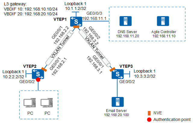
On a network where free mobility is configured, the authentication point and group policy enforcement point for user access are configured on the same device. As a result, the policies of the corresponding group on the entire network need to be configured on the user authentication point, which is not conducive to policy planning. In addition, if a user accesses the network from another authentication point that is not configured with the corresponding group policy, user authorization is affected. To solve this problem, a VXLAN network can be constructed between the user access device and the network resource access device. When an authenticated user who is allocated to a security group accesses network resources through the VXLAN tunnel, the VXLAN packets carry user group information. The network resource access device decapsulates the VXLAN packets, identifies the security group of the user, and can authorize the user using the locally configured group policy.
In Figure 1, VTEP2 functions as the user authentication point. You need to specify a policy for the user to access the mail server. In this case, you can configure a VXLAN network between VTEP2 and VTEP3 to transmit the user group information authorized on VTEP2 to VTEP3 through VXLAN packets. The group policy for accessing the local mail server can be configured on VTEP3.

This example uses the S6730-S, S6730S-S, S5732-H, S5731-S, S5731S-S, S5731S-H, S6730-H, S6730S-H, S5731-H, S5720-HI, S5730-HI, or S6720-HI as an example to describe the configuration.
Data Plan
Device |
VXLAN Tunnel |
BD |
VNI |
Source IP |
Peer IP |
|---|---|---|---|---|---|
VTEP1 |
VTEP1->VTEP2 |
10 |
2010 |
10.1.1.2 |
10.2.2.2 |
VTEP1->VTEP3 |
20 |
2020 |
10.1.1.2 |
10.3.3.2 |
|
VTEP2 |
VTEP2->VTEP1 |
10 |
2010 |
10.2.2.2 |
10.1.1.2 |
VTEP3 |
VTEP3->VTEP1 |
20 |
2020 |
10.3.3.2 |
10.1.1.2 |
Item |
Data |
Description |
|---|---|---|
VTEP2 |
RADIUS authentication server:
|
Configure a RADIUS server to obtain user login and logout information. The port numbers of the authentication server and accounting server must be the same as the authentication and accounting port numbers of the RADIUS server. On the Agile Controller-Campus, the fixed RADIUS authentication and accounting port numbers are 1812 and 1813 respectively. |
RADIUS accounting server:
|
||
XMPP password: Admin@123 |
The configuration is the same as that on the Agile Controller-Campus. |
|
Agile Controller-Campus |
Switch's IP address: 192.168.2.1 |
This is the IP address of GE0/0/1 on VTEP2. |
RADIUS parameters:
|
The configuration is the same as that on VTEP2. |
|
XMPP password: Admin@123 |
The configuration is the same as that on VTEP2. |
|
Account Guest:
|
Authorize the guest group to the guest user. |
|
Security group: Guest_Group Email server: 192.168.20.100 |
- |
|
Pre-authentication domain |
DNS server |
Guests can send domain names to the DNS server for resolution before being authenticated. |
Gateway IP address on VTEP2 |
192.168.10.10 |
- |
Configuration Roadmap
- Configure a routing protocol to ensure connectivity at Layer 3.
- Configure a VXLAN network.
- Configure a deployment mode for the VXLAN access service on VTEP2 and VTEP3.
- Configure information for VXLAN tunnel.
- Configure a Layer 3 VXLAN gateway on VTEP1.
- Configure access authentication on VTEP2.
- Configure access control on VTEP3.
- Configure the Agile Controller-Campus.
Procedure
- Switch the NAC configuration mode to unified mode.
You must switch the NAC configuration mode to unified mode on a switch with the free mobility function configured. The unified mode takes effect after the switch restarts.
<HUAWEI> system-view
[HUAWEI] sysname VTEP2
[VTEP2] authentication unified-mode
- Configure a routing protocol.
# Configure IP addresses for the interfaces on VTEP1. When OSPF is used, the 32-bit loopback address of each switch must be configured.
<HUAWEI> system-view
[HUAWEI] sysname VTEP1
[VTEP1] interface loopback 1
[VTEP1-LoopBack1] ip address 10.1.1.2 32
[VTEP1-LoopBack1] quit
[VTEP1] interface gigabitethernet 0/0/1
[VTEP1-GigabitEthernet0/0/1] undo portswitch
[VTEP1-GigabitEthernet0/0/1] ip address 192.168.2.2 24
[VTEP1-GigabitEthernet0/0/1] quit
[VTEP1] interface gigabitethernet 0/0/2
[VTEP1-GigabitEthernet0/0/2] undo portswitch
[VTEP1-GigabitEthernet0/0/2] ip address 192.168.3.2 24
[VTEP1-GigabitEthernet0/0/2] quit
[VTEP1] interface gigabitethernet 0/0/3
[VTEP1-GigabitEthernet0/0/3] undo portswitch
[VTEP1-GigabitEthernet0/0/3] ip address 192.168.11.1 24
[VTEP1-GigabitEthernet0/0/3] quit
[VTEP1] ospf router-id 10.1.1.2
[VTEP1-ospf-1] area 0
[VTEP1-ospf-1-area-0.0.0.0] network 10.1.1.2 0.0.0.0
[VTEP1-ospf-1-area-0.0.0.0] network 192.168.2.0 0.0.0.255
[VTEP1-ospf-1-area-0.0.0.0] network 192.168.3.0 0.0.0.255
[VTEP1-ospf-1-area-0.0.0.0] network 192.168.11.0 0.0.0.255
[VTEP1-ospf-1-area-0.0.0.0] quit
[VTEP1-ospf-1] quit
# Configure IP addresses for the interfaces on VTEP2.
[VTEP2] interface loopback 1
[VTEP2-LoopBack1] ip address 10.2.2.2 32
[VTEP2-LoopBack1] quit
[VTEP2] interface gigabitethernet 0/0/1
[VTEP2-GigabitEthernet0/0/1] undo portswitch
[VTEP2-GigabitEthernet0/0/1] ip address 192.168.2.1 24
[VTEP2-GigabitEthernet0/0/1] quit
[VTEP2] ospf router-id 10.2.2.2
[VTEP2-ospf-1] area 0
[VTEP2-ospf-1-area-0.0.0.0] network 10.2.2.2 0.0.0.0
[VTEP2-ospf-1-area-0.0.0.0] network 192.168.2.0 0.0.0.255
[VTEP2-ospf-1-area-0.0.0.0] quit
[VTEP2-ospf-1] quit
# Configure IP addresses for the interfaces on VTEP3.
<HUAWEI> system-view
[HUAWEI] sysname VTEP3
[VTEP3] interface loopback 1
[VTEP3-LoopBack1] ip address 10.3.3.2 32
[VTEP3-LoopBack1] quit
[VTEP3] interface gigabitethernet 0/0/1
[VTEP3-GigabitEthernet0/0/1] undo portswitch
[VTEP3-GigabitEthernet0/0/1] ip address 192.168.3.1 24
[VTEP3-GigabitEthernet0/0/1] quit
[VTEP3] ospf router-id 10.3.3.2
[VTEP3-ospf-1] area 0
[VTEP3-ospf-1-area-0.0.0.0] network 10.3.3.2 0.0.0.0
[VTEP3-ospf-1-area-0.0.0.0] network 192.168.3.0 0.0.0.255
[VTEP3-ospf-1-area-0.0.0.0] quit
[VTEP3-ospf-1] quit
# After OSPF is configured, the VTEP can learn the loopback interface address of each other and successfully ping each other. The following shows the ping result from VTEP2 to VTEP3.
[VTEP2] ping 10.3.3.2 PING 10.3.3.2: 56 data bytes, press CTRL_C to break Reply from 10.3.3.2: bytes=56 Sequence=1 ttl=255 time=240 ms Reply from 10.3.3.2: bytes=56 Sequence=2 ttl=255 time=5 ms Reply from 10.3.3.2: bytes=56 Sequence=3 ttl=255 time=5 ms Reply from 10.3.3.2: bytes=56 Sequence=4 ttl=255 time=14 ms Reply from 10.3.3.2: bytes=56 Sequence=5 ttl=255 time=5 ms --- 10.3.3.2 ping statistics --- 5 packet(s) transmitted 5 packet(s) received 0.00% packet loss round-trip min/avg/max = 5/53/240 ms - Configure a VXLAN network.
Configure a service access point on VTEP2 and VTEP3, respectively.
# Configure VTEP2.
[VTEP2] vlan 10
[VTEP2-vlan10] quit
[VTEP2] bridge-domain 10
[VTEP2-bd10] l2 binding vlan 10
[VTEP2-bd10] vxlan vni 2010
[VTEP2-bd10] quit
[VTEP2] interface gigabitethernet 0/0/2
[VTEP2-GigabitEthernet0/0/2] port link-type access
[VTEP2-GigabitEthernet0/0/2] port default vlan 10
[VTEP2-GigabitEthernet0/0/2] quit
# Configure VTEP3.
[VTEP3] vlan 20
[VTEP3-vlan20] quit
[VTEP3] bridge-domain 20
[VTEP3-bd20] l2 binding vlan 20
[VTEP3-bd20] vxlan vni 2020
[VTEP3-bd20] quit
[VTEP3] interface gigabitethernet 0/0/2
[VTEP3-GigabitEthernet0/0/2] port link-type access
[VTEP3-GigabitEthernet0/0/2] port default vlan 20
[VTEP3-GigabitEthernet0/0/2] quit
Configure information for VXLAN tunnel.
# Configure VTEP1.
[VTEP1] bridge-domain 10
[VTEP1-bd10] vxlan vni 2010
[VTEP1-bd10] quit
[VTEP1] bridge-domain 20
[VTEP1-bd20] vxlan vni 2020
[VTEP1-bd20] quit
[VTEP1] interface nve 1
[VTEP1-Nve1] source 10.1.1.2
[VTEP1-Nve1] vni 2010 head-end peer-list 10.2.2.2
[VTEP1-Nve1] vni 2020 head-end peer-list 10.3.3.2
[VTEP1-Nve1] quit
# Configure VTEP2.
[VTEP2] interface nve 1
[VTEP2-Nve1] source 10.2.2.2
[VTEP2-Nve1] vni 2010 head-end peer-list 10.1.1.2
[VTEP2-Nve1] quit
# Configure VTEP3.
[VTEP3] interface nve 1
[VTEP3-Nve1] source 10.3.3.2
[VTEP3-Nve1] vni 2020 head-end peer-list 10.1.1.2
[VTEP3-Nve1] quit
Configure a Layer 3 VXLAN gateway on VTEP1.
# Configure VTEP1.
[VTEP1] interface vbdif 10
[VTEP1-Vbdif10] ip address 192.168.10.10 24
[VTEP1-Vbdif10] quit
[VTEP1] interface vbdif 20
[VTEP1-Vbdif20] ip address 192.168.20.10 24
[VTEP1-Vbdif20] quit
- Configure NAC on VTEP2.
# Configure parameters for interconnection with the RADIUS server.
[VTEP2] radius-server template policy    //Create RADIUS server template policy.
[VTEP2-radius-policy] radius-server authentication 192.168.11.10 1812    //Configure the IP address and port number (1812) for the RADIUS authentication server.
[VTEP2-radius-policy] radius-server accounting 192.168.11.10 1813    //Configure the IP address and port number (1813) for the RADIUS accounting server.
[VTEP2-radius-policy] radius-server shared-key cipher Admin@123        //Configure a RADIUS shared key.
[VTEP2-radius-policy] quit
[VTEP2] radius-server authorization 192.168.11.10 shared-key cipher Admin@123    //Configure the IP address and shard key for the authorization server.
[VTEP2] aaa
[VTEP2-aaa] authentication-scheme auth    //Create authentication scheme auth.
[VTEP2-aaa-authen-auth] authentication-mode radius    //Set the authentication mode to RADIUS.
[VTEP2-aaa-authen-auth] quit
[VTEP2-aaa] accounting-scheme acco    //Create accounting scheme acco.
[VTEP2-aaa-accounting-acco] accounting-mode radius    //Set the accounting mode to RADIUS.
[VTEP2-aaa-accounting-acco] accounting realtime 15    //Set the real-time accounting interval to 15 minutes.
[VTEP2-aaa-accounting-acco] quit
[VTEP2-aaa] domain default    //Enter the default domain, bind the RADIUS server template, authentication scheme, and accounting scheme.
[VTEP2-aaa-domain-default] radius-server policy
[VTEP2-aaa-domain-default] authentication-scheme auth
[VTEP2-aaa-domain-default] accounting-scheme acco
[VTEP2-aaa-domain-default] quit
[VTEP2-aaa] quit
# Configure NAC.
By default, an 802.1X access profile uses the EAP authentication mode. Ensure that the RADIUS server supports EAP; otherwise, the server cannot process 802.1X authentication request packets.
[VTEP2] dot1x-access-profile name d1
[VTEP2-dot1x-access-profile-d1] quit
[VTEP2] free-rule-template name default_free_rule
[VTEP2-free-rule-default_free_rule] free-rule 1 destination ip 192.168.11.20 mask 24 source ip any    //Ensure that users can access the DNS server before being authenticated.
[VTEP2-free-rule-default_free_rule] quit
[VTEP2] authentication-profile name p1
[VTEP2-authen-profile-p1] dot1x-access-profile d1
[VTEP2-authen-profile-p1] access-domain default
[VTEP2-authen-profile-p1] quit
[VTEP2] interface gigabitethernet 0/0/2
[VTEP2-GigabitEthernet0/0/2] authentication-profile p1
[VTEP2-GigabitEthernet0/0/2] quit
- Configure an ACL on VTEP3.
[VTEP3] acl 6000
[VTEP3-acl-ucl-6000] rule 10 deny ip source ucl-group 1 destination 192.168.20.100 0
[VTEP3-acl-ucl-6000] quit
[VTEP3] traffic-filter inbound acl 6000
- Configure XMPP parameters for interworking with the Agile Controller-Campus, and enable free mobility.
[VTEP2] group-policy controller 192.168.11.10 password Admin@123 src-ip 192.168.2.1
[VTEP2] quit
<VTEP2> save
- Configure the Agile Controller-Campus.
- Add switches.
- Choose , and click Add.
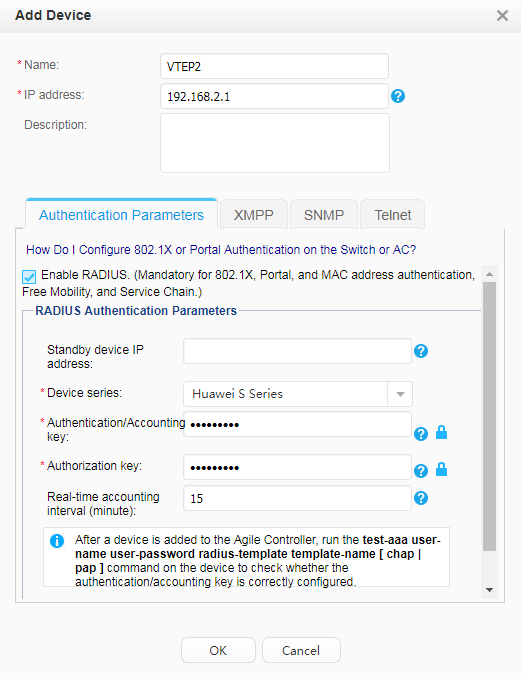
- Click the XMPP tab.
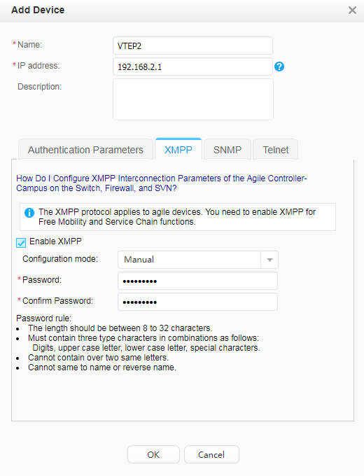
- Click OK. The switch's Status is
 and Synchronization Status is Success.
 - On VTEP2, check the switch's communication status with the Agile Controller-Campus.
<VTEP2> display group-policy status
Controller IP address: 192.168.11.10
Controller port: 5222
Backup controller IP address: -
Backup controller port: -
Source IP address: 192.168.2.1
State: working
Connected controller: master
Device protocol version: 1
Controller protocol version: 1
- Choose , and click Add.
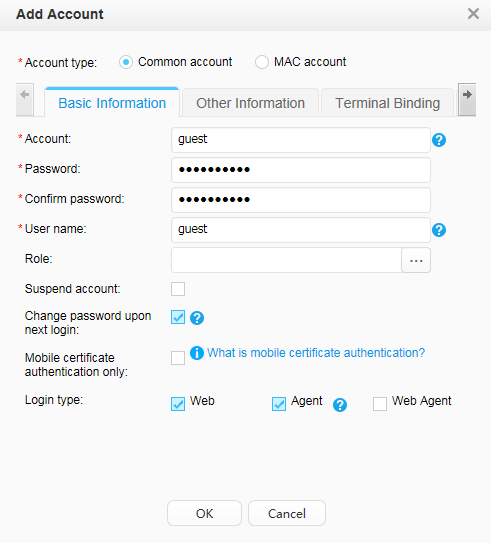
- Create the guest account.
- Choose .
- Click Add and create the guest account.
- Configure a guest group to indicate users.
- Choose .
- Click Add and create Guest_Group.
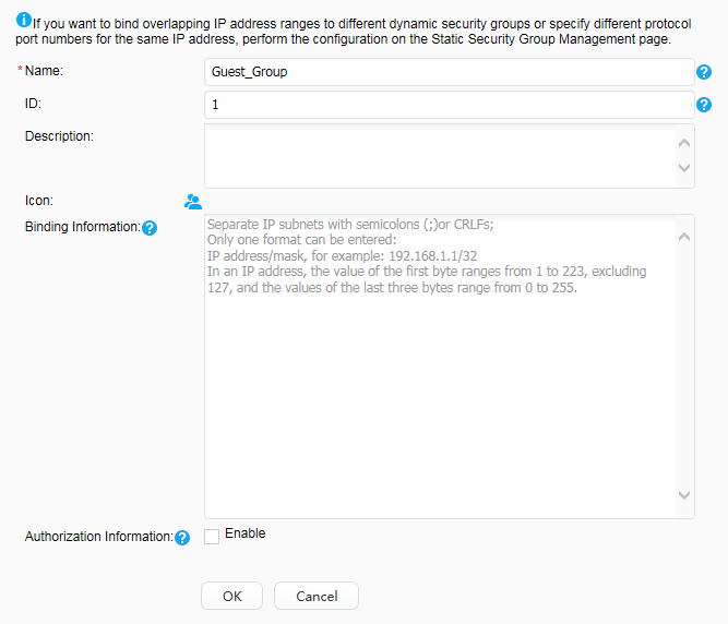
- Click Global Deployment to deploy the security group on the entire network.
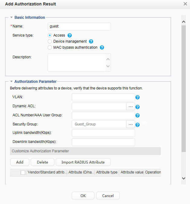
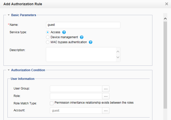
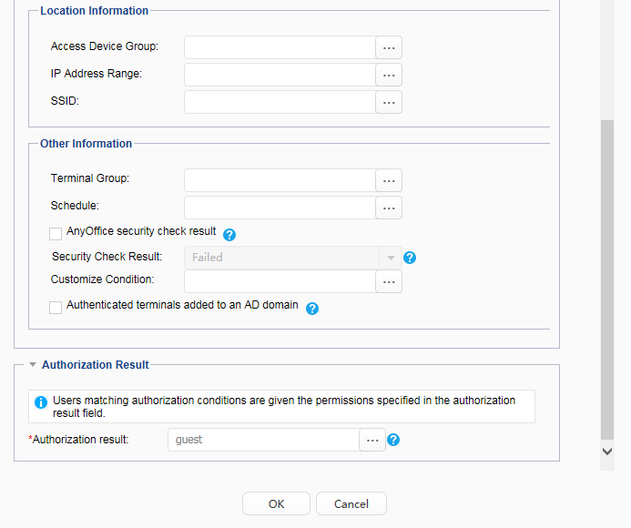
- Authorize the security group Guest_Group to guests. Guests are mapped to the security group Guest_Group after being authenticated.
- Add switches.
- Verify the configuration.
# After the preceding configuration, run the display vxlan vni and display vxlan tunnel commands on VTEP1, VTEP2, and VTEP3. You can view that the VNI status is Up and VXLAN tunnel information is displayed. The command output of VTEP1 is used as an example.
<VTEP1> display vxlan vni
 VNI               BD-ID             State
 -----------------------------------------
 2010              10                up
 2020              20                up
 -----------------------------------------
 Number of vxlan vni bound to BD is : 2

 VNI               VRF-ID
 -----------------------------------------
 -----------------------------------------
 Number of vxlan vni bound to VPN is : 0
<VTEP1> display vxlan tunnel
 Tunnel ID       Source              Destination         State     Type
 ----------------------------------------------------------------------------
 4026531842      10.1.1.2             10.2.2.2             up        static
 4026531841      10.1.1.2             10.3.3.2             up        static
 ----------------------------------------------------------------------------
 Number of vxlan tunnel :
 Total : 2    Static: 2    L2 dynamic: 0    L3 dynamic: 0
# After the configuration is complete, users in different network segments can communicate over VXLAN tunnels.
# Users cannot access the email server after being authenticated by VTEP2.

Configuration Files
-
#
sysname VTEP1
#
bridge-domain 10
 vxlan vni 2010
bridge-domain 20
 vxlan vni 2020
#
interface GigabitEthernet0/0/1
 undo portswitch
 ip address 192.168.2.2 255.255.255.0
#
interface GigabitEthernet0/0/2
 undo portswitch
 ip address 192.168.3.2 255.255.255.0
#
interface GigabitEthernet0/0/3
 undo portswitch
 ip address 192.168.11.1 255.255.255.0
#
interface LoopBack1
 ip address 10.1.1.2 255.255.255.255
#
interface Vbdif10
 ip address 192.168.10.10 255.255.255.0
#
interface Vbdif20
 ip address 192.168.20.10 255.255.255.0
#
interface Nve1
 source 10.1.1.2
 vni 2010 head-end peer-list 10.2.2.2
 vni 2020 head-end peer-list 10.3.3.2
#
ospf 1 router-id 10.1.1.2
 area 0.0.0.0
  network 10.1.1.2 0.0.0.0
  network 192.168.2.0 0.0.0.255
  network 192.168.3.0 0.0.0.255
  network 192.168.11.0 0.0.0.255
#
return
-
#
sysname VTEP2
#
vlan batch 10
#
authentication-profile name p1
 dot1x-access-profile d1
 access-domain default
#
group-policy controller 192.168.11.10 password %^%#(K2]5P#C6'97.pR(gFv$K$KbGYN}R1Y76~K^;AP&%^%# src-ip 192.168.2.1
#
radius-server template policy
 radius-server shared-key cipher %^%#teXm2B&.1O0:cj$OWPq7@!Y\!%}dC3Br>p,}l\L.%^%#
 radius-server authentication 192.168.11.10 1812 weight 80
 radius-server accounting 192.168.11.10 1813 weight 80
radius-server authorization 192.168.11.10 shared-key cipher %^%#FKIlCKv=f(AgM-G~W"}G.C\%;b'3A/zz-EJV;vi*%^%#
#
free-rule-template name default_free_rule
 free-rule 1 destination ip 192.168.11.20 mask 255.255.255.0 source ip any
#
aaa
 authentication-scheme auth
  authentication-mode radius
 accounting-scheme acco
  accounting-mode radius
  accounting realtime 15
 domain default
  authentication-scheme auth
  accounting-scheme acco
  radius-server policy
#
bridge-domain 10
 l2 binding vlan 10
 vxlan vni 2010
#
interface GigabitEthernet0/0/1
 undo portswitch
 ip address 192.168.2.1 255.255.255.0
#
interface GigabitEthernet0/0/2
 port link-type access
 port default vlan 10
 authentication-profile p1
#
interface LoopBack1
 ip address 10.2.2.2 255.255.255.255
#
interface Nve1
 source 10.2.2.2
 vni 2010 head-end peer-list 10.1.1.2
#
ospf 1 router-id 10.2.2.2
 area 0.0.0.0
  network 10.2.2.2 0.0.0.0
  network 192.168.2.0 0.0.0.255
#
dot1x-access-profile name d1
#
return
-
#
sysname VTEP3
#
vlan batch 20
#
acl number 6000
 rule 10 deny ip source ucl-group 1 destination 192.168.20.100 0
#
bridge-domain 20
 l2 binding vlan 20
 vxlan vni 2020
#
interface GigabitEthernet0/0/1
 undo portswitch
 ip address 192.168.3.1 255.255.255.0
#
interface GigabitEthernet0/0/2
 port link-type access
 port default vlan 20
#
interface LoopBack1
 ip address 10.3.3.2 255.255.255.255
#
interface Nve1
 source 10.3.3.2
 vni 2020 head-end peer-list 10.1.1.2
#
ospf 1 router-id 10.3.3.2
 area 0.0.0.0
  network 10.3.3.2 0.0.0.0
  network 192.168.3.0 0.0.0.255
#
traffic-filter inbound acl 6000
#
return