Example for Configuring SVF
Networking Requirements
A new campus network has a large number of wired and wireless access devices. The widely distributed access devices complicate management and configuration of the access layer. Unified management and configuration of wired and wireless access devices are required to reduce the management cost.
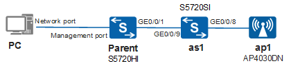
In Figure 1, the parent is directly connected to a level-1 AS, and the level-1 AS is directly connected to an AP. The PC's network port is directly connected to the parent's Ethernet management port for a login to the web system to configure SVF.
This configuration example uses the S5720-HI as the parent, an S5720-SI as the level-1 AS, and an AP4030DN as the AP. Both the parent and level-1 AS use the software version V200R010C00, and the AP uses the software version V200R007C10.
Configuration Roadmap
- Log in to the web system of the parent through the PC and ensure that the PC and parent reside on the same network segment.
- Change to the SVF mode.
- Configure the SVF system capability.
- Enable SVF and configure the management VLAN ID and management IP address.
- Add the level-AS.
- Add the AP.
- Clear the AS configuration and restart it to ensure that this unconfigured AS can be connected to the SVF system. Connect the level-1 AS to the parent and connect the AP to the level-1 AS using cables.
- Check whether the SVF configuration is correct.
Data Plan
Item |
Data |
|---|---|
MAC addresses of the parent, AS1 and AP1 |
Parent: 0500-0000-XXXX AS1: 88cf-98ba-XXXX AP1: fcb6-98d6-XXXX |
SVF management VLAN |
VLAN 4090 |
IP address of the management VLANIF |
192.168.2.1 |
Port that connects the parent to AS1 |
GE0/0/1 |
Port that connects the AS1 to parent |
GE0/0/9 NOTE:
If the AS needs to use downlink service ports as member ports of the connected uplink fabric port, you need to run the command to specify these downlink service ports as member ports of the connected uplink fabric port. For details, see Configuring an AS in "SVF Configuration" in the S2720, S5700, and S6700 V200R019C10 Configuration Guide - Device Management. |
Port that connects AS1 to AP1 |
GE0/0/8 |
AP SN |
21500826412SF690XXXX |
Procedure
- Log in to the web system of the parent through the PC.
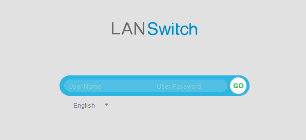
- Open the web browser on the PC, enter https://management address of the parent in the address box, and press Enter. The web system login page is displayed, as shown in Figure 2.
- Change to the SVF mode.
- Enable the SVF function on the parent.
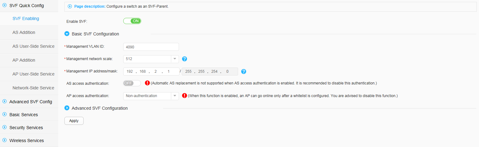
- Set Enable SVF to ON. The SVF Enabling page is displayed, as shown in Figure 5.Perform the following configurations:
- Set Management VLAN ID to 4090.
- Set Management network scale to 512.
- Set Management IP address/mask to 192.168.2.1/255.255.254.0.
- Set AS access authentication to OFF.
- Set AP access authentication to Non-authentication.
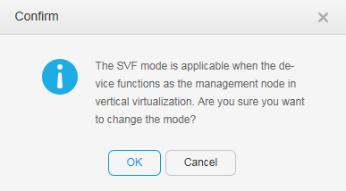
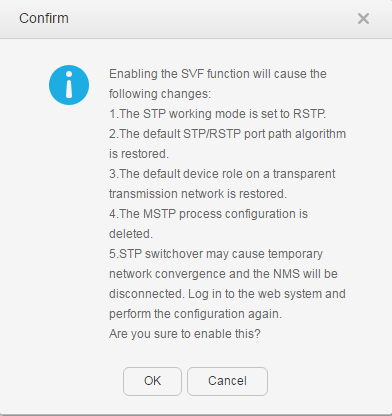
- Click Apply. In the dialog box that is displayed, click OK, as shown in Figure 6.
When an operation success message is displayed, click OK.
- Set Enable SVF to ON. The SVF Enabling page is displayed, as shown in Figure 5.
- Add AS1.
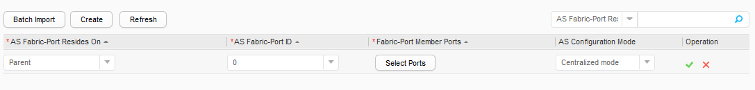
- Click Create and set AS Fabric-Port Resides On to Parent and AS Fabric-Port ID to 0, as shown in Figure 7.
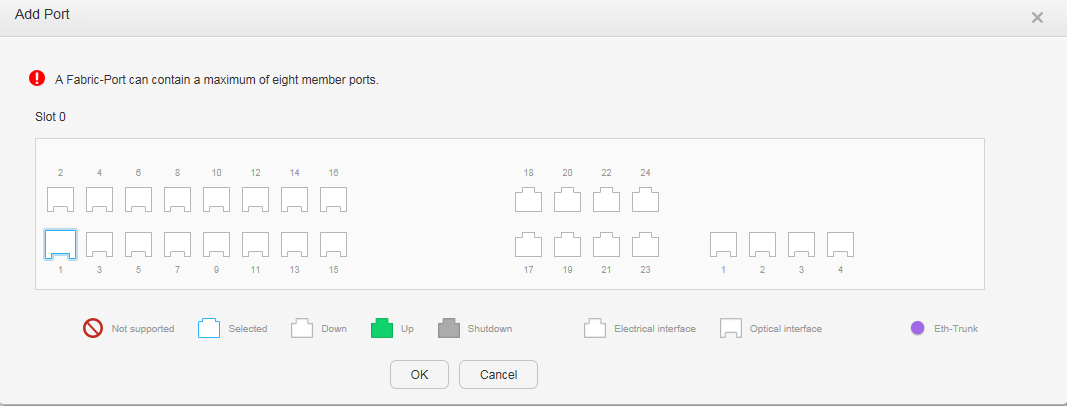
- Click Select Ports in Fabric-Port Member Ports. In the displayed Add Port dialog box, select GE0/0/1 (the port connected to AS1) as the fabric-port, and click OK, as shown in Figure 8.
- Choose Centralized mode for AS Configuration Mode. After the configurations are complete, click
 .
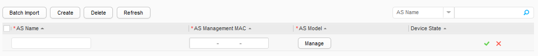
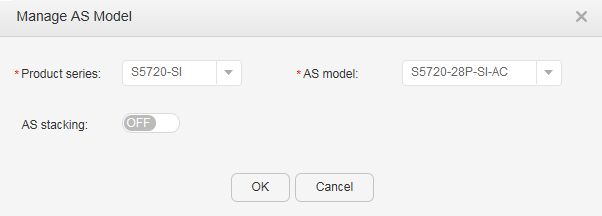
. - Click Create, as shown in Figure 9.
- Click Manage below AS Model. The Manage AS Model dialog box is displayed, as shown in Figure 10. Set Product series to S5720-SI, AS model to S5720-28P-SI-AC, and AS stacking to OFF, and click OK.
- After the configurations are complete, click .
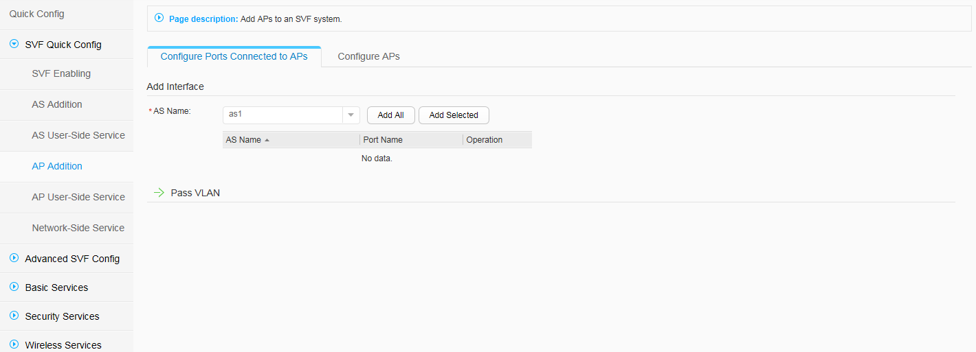
- Add AP1.
- Choose and click the Configure Ports Connected to APs tab. Select as1 from AS Name, as shown in Figure 11.
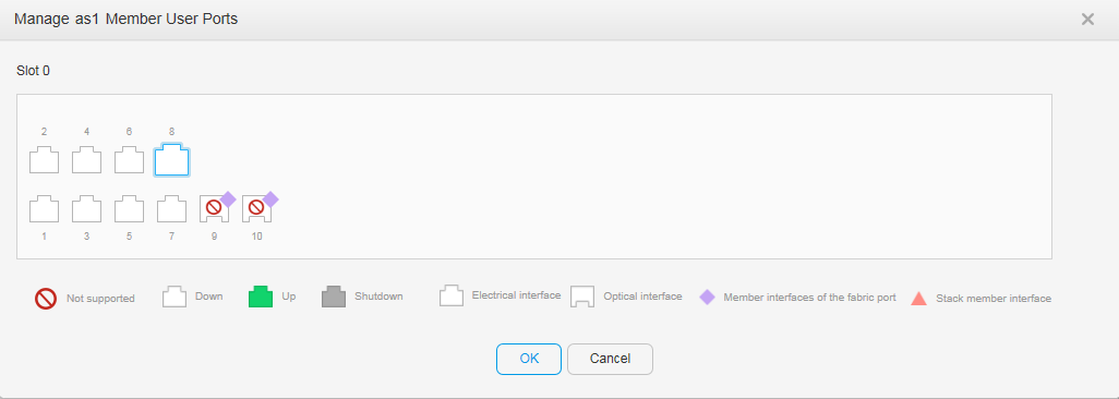
- Click Add Selected and select GE0/0/8 from the displayed Manage as1 Member User Ports dialog box, as shown in Figure 12.
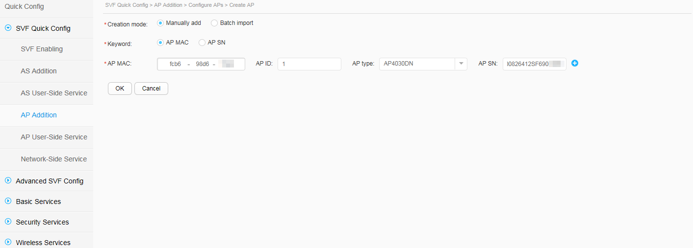
- Click the Configure APs tab, click Create to set AP parameters, and click OK after setting these parameters, as shown in Figure 13.Perform the following configurations:
- Set Creation mode to Manually add.
- Set Keyword to AP MAC.
- Set AP MAC to fcb6-98d6-XXXX.
- Set AP ID to 1.
- Set AP type to AP4030DN.
- Set AP SN to 21500826412SF690XXXX.
- Log in to the AS using a command, run the reset saved-configuration command to clear the AS configuration, and reboot the AS. If the system asks you whether to save the current configuration during the reboot, enter N. Connect the level-1 AS to the parent and connect the AP to the level-1 AS using cables.


Result
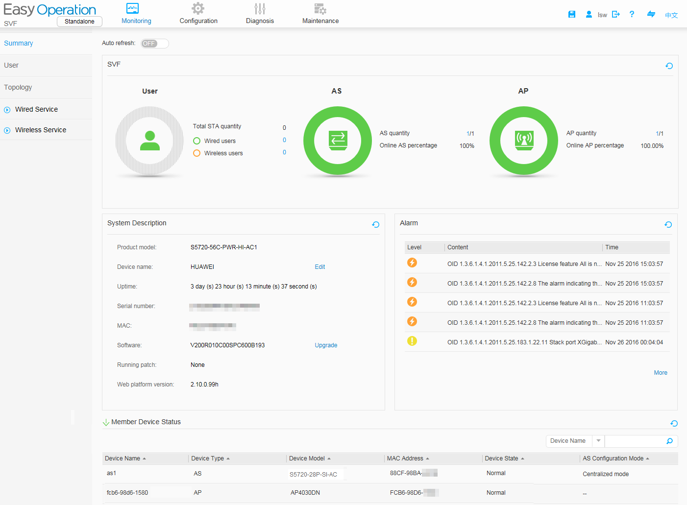
- Choose . In the displayed page, you can view SVF overview and device status information. Click
 on the left side of Member Device Status, and you can view that both the AS and AP are online, as shown in Figure 14. This indicates that an SVF system has been set up.
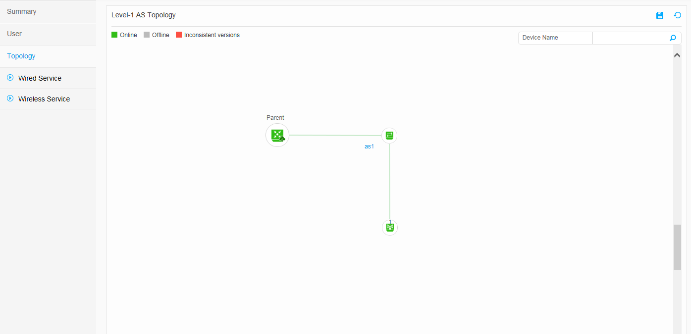
- Check the SVF topology.