Example for Configuring IPv4 Static Routes
Networking Requirements
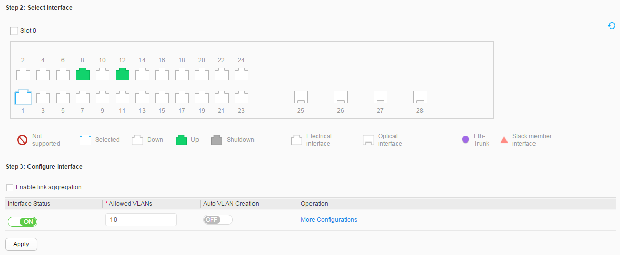
In Figure 1, PC1, PC2, and PC3 are on different network
segments, and are connected through SwitchA, SwitchB, and SwitchC. Any two PCs must be connected
using static routes to communicate with each other without using dynamic
routing protocols.
Configuration Roadmap
The configuration roadmap is as follows:
- Create VLANs, add interfaces to VLANs, and assign IPv4 addresses to VLANIF interfaces so that neighboring devices can communicate with each other.
- Configure an IPv4 default gateway on each PC, and configure IPv4 static routes or default static routes on each Switch so that any two PCs on different network segments can communicate with each other.
Procedure
- Configure VLANs to which interfaces belong. The following
example configures SwitchA. The configurations of SwitchB and SwitchC
are similar to the configuration of SwitchA.
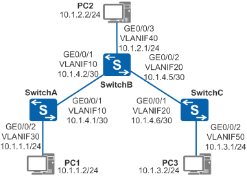
- Select GE0/0/2 under Step 2: Select Interface, and set Interface Status and Default VLAN under Step 3: Configure Interface to ON and 30, as shown in Figure 2. You do not need to configure other parameters under Step 3: Configure Interface.
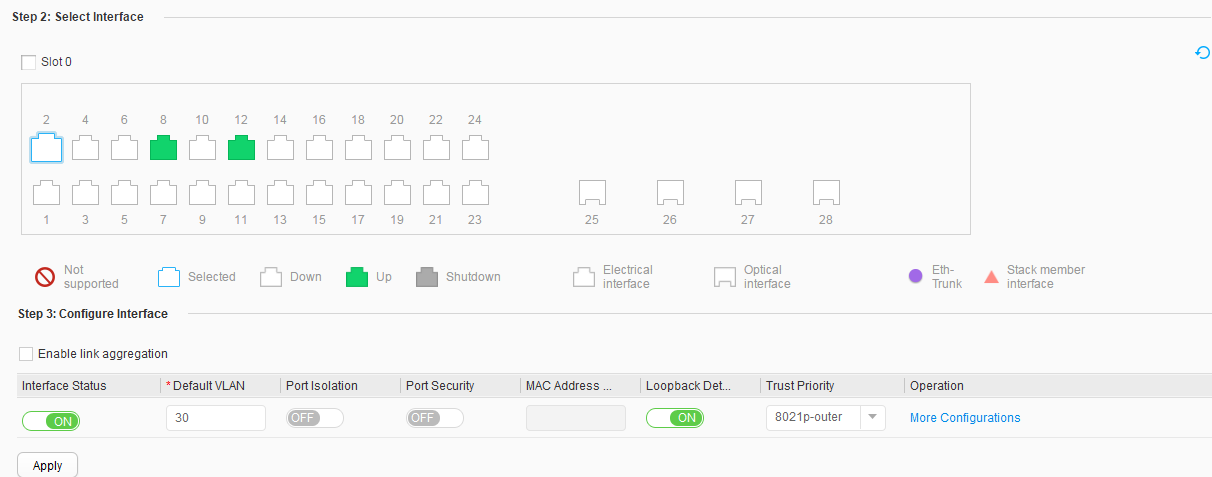
- Click Connect to Switch, select GE0/0/1 under Step 2: Select Interface, and set Interface Status, Allowed VLANs, and Auto VLAN Creation under Step 3: Configure Interface to ON, 10, and OFF, as shown in Figure 3. You do not need to configure other parameters under Step 3: Configure Interface.
- Configure an IP address for each VLANIF interface. The
following example configures SwitchA. The configurations of SwitchB
and SwitchC are similar to the configuration of SwitchA.
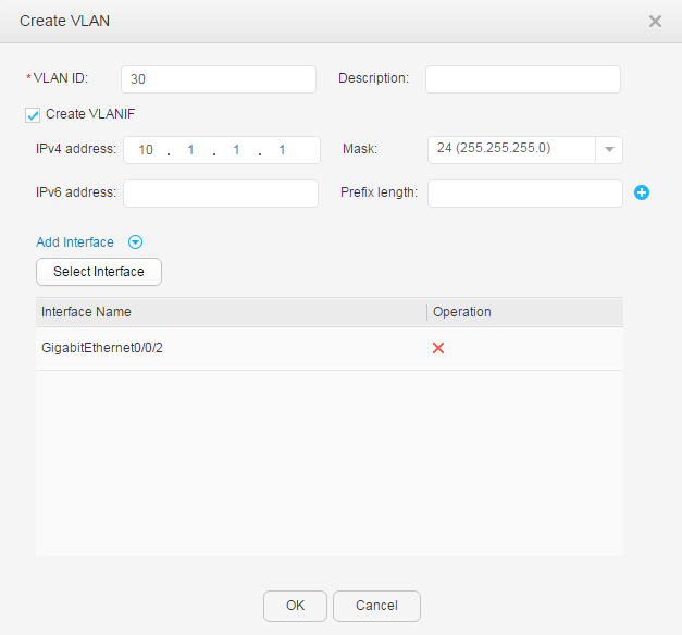
- Click Create and set parameters,
as shown in Figure 4.
Configure GE0/0/2:
- Set VLAN ID to 30.
- Select Create VLANIF.
- Set IPv4 address/Mask to 10.1.1.1/24.
- Click Add Interface, click Select Interface to open the Add Interface page, select GE0/0/2, and click OK.
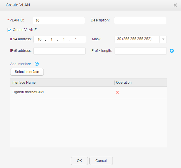
Configure GE0/0/1:
- Set VLAN ID to 10.
- Select Create VLANIF.
- Set IPv4 address/Mask to 10.1.4.1/30.
- Click Add Interface, click Select Interface to open the Add Interface page, select GE0/0/1, and click OK.
- Click Create and set parameters,
as shown in Figure 4.
- Configure PCs.
Set the default gateway addresses of PC1, PC2, and PC3 to 10.1.1.1, 10.1.2.1, and 10.1.3.1 respectively.
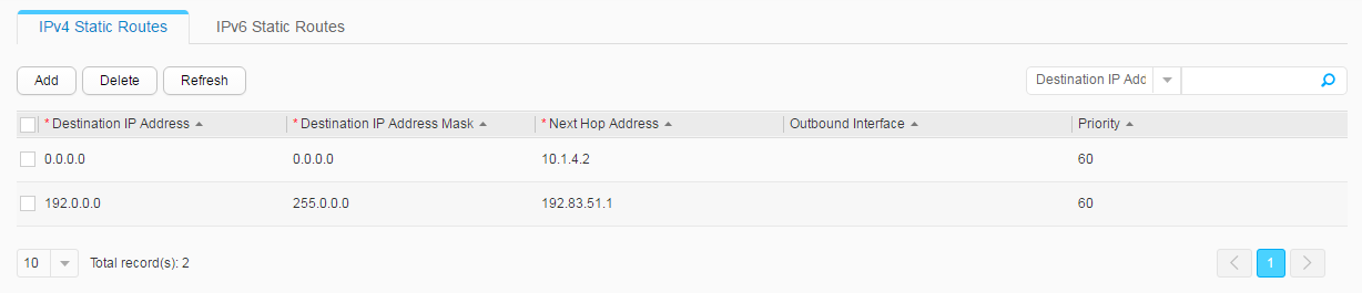
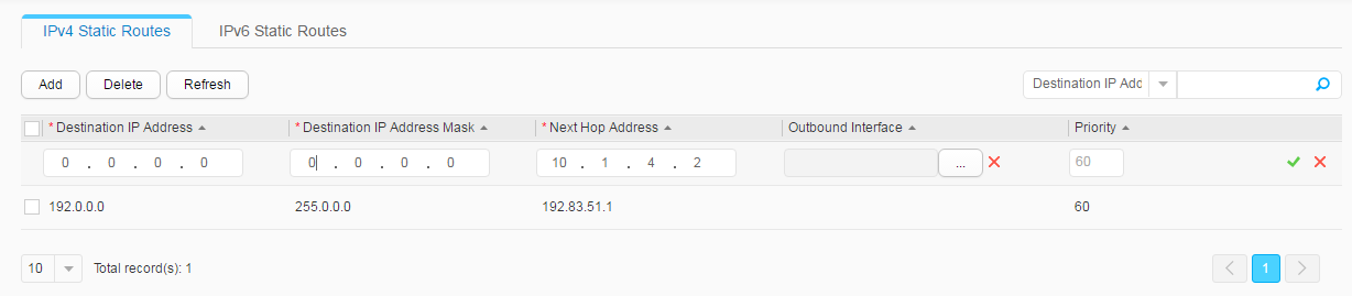
- Configure static routes. The following example configures SwitchA. The configurations of SwitchB and SwitchC are similar to the configuration of SwitchA.

Operation Result
The following example displays the configuration of SwitchA. You can also use this method to view the configurations of SwitchB and SwitchC.
Choose to view routing information, as shown in Figure 6.
- PC1 can communicate with PC2 and PC3.