Detect Link
Context
Virtual cable test (VCT) technology uses time domain reflectometry (TDR) to detect the cable status. When a pulse is transmitted to the end of a cable or a failure point in the cable, some pulse energies are reflected to the transmitting end. The VCT algorithm measures the time spent on transmitting pulses over a cable, reaching a failure point, and returning the pulses. The measured time is converted to the distance.
VCT can detect the fault type of a network cable and identify failure points to help locate network cable faults.
The VCT test result is only for reference and may be inaccurate for cables of some vendors.
VCT takes effect only on optical interfaces that have GE copper modules installed or GE electrical interfaces on the device.


If the switch does not support the MEth port, click to access the configuration page.
Procedure
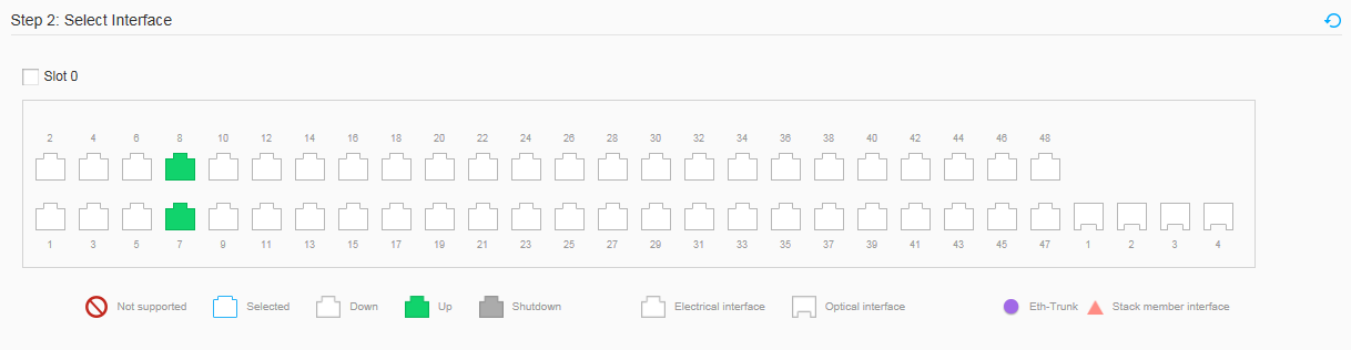
- Choose . Click Detect Link, as shown in Figure 2.
- Select the interface that you want to configure. Perform either of the following operations as required.
- Click an interface icon to select an interface.
- Drag the mouse to select multiple consecutive interfaces in a batch.
- Click multiple port icons to select these ports, and click a port icon again to deselect the port.
- Click the check box before a front panel name to select all the interfaces on the front panel.
- Click Apply. In the dialog box that is displayed, click OK.
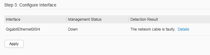
- You can view check results on the Configure Interface. Figure 3 shows the Configure Interface.
Table 1 describes the parameters on the Configure Interface.
Table 1 Parameters on the Configure Interface Item
Description
Interface
Type and number of the interface on which link detection is performed.
Management Status
Management status of the interface.- Down: The interface is disabled.
- Up: The interface is enabled.
- Shutdown: indicates that the administrator has run the shutdown command on the interface.
Detection Result
Link detection result, which can be either The network cable is faulty or The interface works normally.NOTE:If network cable faults occur, click Details to view the detailed detection result. The displayed page contains the following fields:- Pair A/B/C/D: indicates the 4 pairs of circuits in a network cable.
- Pair A length: indicates the length of a network cable. If a fault occurs, this field indicates the distance between the interface and the location of the fault; when the network cable works properly, this field indicates the actual length of the cable; If the interface is not connected to any network cable, the default length is 0 meters.
- Pair A state: indicates the status of a network cable. (OK: normal; Open: open-circuited; Short: short-circuited; Crosstalk: incorrect cable sequence; Unknown: unknown fault)