AS User-Side Service
Procedure
- Choose . The AS User-Side Service page is displayed, as shown in Figure 1.
- Click
 in the same row as AS name, and select the corresponding AS from the displayed list of available ASs.
 - Click OK. The configuration page is displayed.
- Select the interfaces to be configured by performing any of the following operations based on actual requirements:
- Click an interface icon to select an interface. You can click the icon again to deselect the interface.
- Drag the mouse to select continuous interfaces in batches.
- Click multiple interface icons to select them. You can click a certain icon again to deselect the interface.
- Select the check box in the upper left corner to select all the interfaces.
- Perform service configuration based on the connection type.
Table 1 Icons on the Service Configuration tab Icon
Description

Select: allows you to select parameters.

Create: allows you to configure parameters.

Modify: allows you to modify parameters.

Delete: allows you to delete currently configured parameters.
- Set Connection type to User-defined, as shown in Figure 2.
- Select the network basic profile. The profile can be created in AS Profile Mgmt.
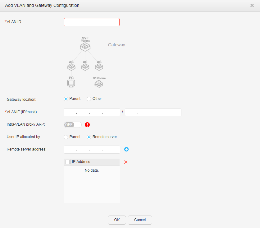
- Click next to Default VLAN. The Add VLAN and Gateway Configuration dialog box is displayed, as shown in Figure 3.
Table 2 describes the parameters in the Add VLAN and Gateway Configuration dialog box.
Table 2 Parameters in the Add VLAN and Gateway Configuration dialog box Item
Description
VLAN ID
Indicates a VLAN ID. The value ranges from 1 to 4094.
Gateway location
Sets Gateway location to Parent or Other.
VLANIF (IP/mask)
Specifies the IP address and mask of the gateway.
Intra-VLAN proxy ARP
Indicates whether to enable ARP proxy in a VLAN:- ON: Enable ARP proxy.
- OFF: Disable ARP proxy.
NOTE:In centralized forwarding, ARP proxy must be enabled in a VLAN.
User IP allocated by
Specifies the user IP address allocation mode:- Parent
- Remote server
Remote server address
Specifies the IP address of a remote server. After setting an IP address, click
 to add it to the following list.NOTE:
This parameter is displayed when User IP allocated by is set to Remote server.
- Configure the parameters and click OK.
- Click next to Voice VLAN. The Add VLAN and Gateway Configuration dialog box is displayed, as shown in Figure 3.
Table 2 describes the parameters in the Add VLAN and Gateway Configuration dialog box.
- Configure the parameters and click OK.
- Enter a VLAN ID for transparent transmission.
- Click next to Network Enhanced Profile. The Add Network Enhanced Profile dialog box is displayed, as shown in Figure 4.
Table 3 describes the parameters in the Add Network Enhanced Profile dialog box.
Table 3 Parameters in the Add Network Enhanced Profile dialog box Item
Description
Profile name
Specifies the enhanced service template name.
Port group authentication
Specifies the port group authentication status:- Enabled
- Disabled
Unicast suppression (pps)
Sets the maximum unknown unicast traffic allowed on an interface. The value ranges from 0 to 1488100.
Broadcast suppression (pps)
Sets the maximum broadcast traffic allowed on an interface. The value ranges from 0 to 1488100.
Multicast suppression (pps)
Sets the maximum multicast traffic allowed on an interface. The value ranges from 0 to 1488100.
All traffic suppression (kbps)
Sets the maximum traffic allowed on an interface. The value ranges from 64 to 10000000.
DHCP Snooping
Indicates whether to enable DHCP snooping:- ON: Enable DHCP snooping.
- OFF: Disable DHCP snooping.
IPSG
Indicates whether to enable IP source guard:- ON: Enable IP source guard.
- OFF: Disable IP source guard.
This parameter is configurable only after the DHCP Snooping is enabled.
DAI
Indicates whether to enable ARP inspection:- ON: Enable ARP inspection.
- OFF: Disable ARP inspection.
This parameter is configurable only after the DHCP Snooping is enabled.
Edge Port
Indicates whether to enable the edge port function on an interface:- ON: Enable the edge port function.
- OFF: Disable the edge port function.
- Configure the parameters and click OK.
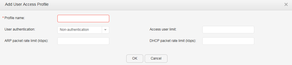
- Click next to User Access Profile. The Add User Access Profile dialog box is displayed.
- Set User authentication to Non-authentication, as shown in Figure 5.
Table 4 describes the parameters on the page.
Table 4 Creating a user access profile: non-authentication Item
Description
Profile name
Specifies the name of a user access control template.
Access user limit
Sets the maximum number of access users. The value ranges from 0 to 4096.
ARP packet rate limit (kbps)
Sets the rate limit of incoming ARP packets on an interface. The value ranges from 8 to 128.
DHCP packet rate limit (kbps)
Sets the rate limit of incoming DHCP packets on an interface. The value ranges from 8 to 128.
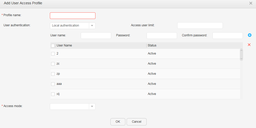
- Set User authentication to Local authentication, as shown in Figure 6.
Table 5 describes the parameters on the page.
Table 5 Creating a user access profile: local authentication Item
Description
Profile name
Specifies the name of a user access control template.
Access user limit
Sets the maximum number of access users. The value ranges from 1 to 512.
User Name
Creates the local user name.
Password
Creates the local password.
Confirm password
Confirms the local password.
Access mode
Sets the user access authentication mode. You can select one or more from the following authentication modes:
- MAC: MAC address authentication
- 802.1X: 802.1X authentication
- Portal: Portal authentication
Portal Server
When Access mode includes Portal, the following parameters are valid:
Portal server name
Specifies the name of a Portal server template.
Source IP
Indicates the source IP address for the device to communicate with a Portal server.
URL
Sets a URL for a Portal server. The URL identifies the Portal server's website that can be visited by Portal authentication users.
Portal server IP
Configures an IP address for the Portal server.
Port number
Configures a destination port number for the device to send packets to the Portal server.
The value is an integer that ranges from 1 to 65535.
Shared key
Configures a shared key used by the device to exchange information with the Portal server.
The value is a string of 1 to 16 characters.
Confirm shared key
Confirms the shared key used by the device to exchange information with the Portal server.
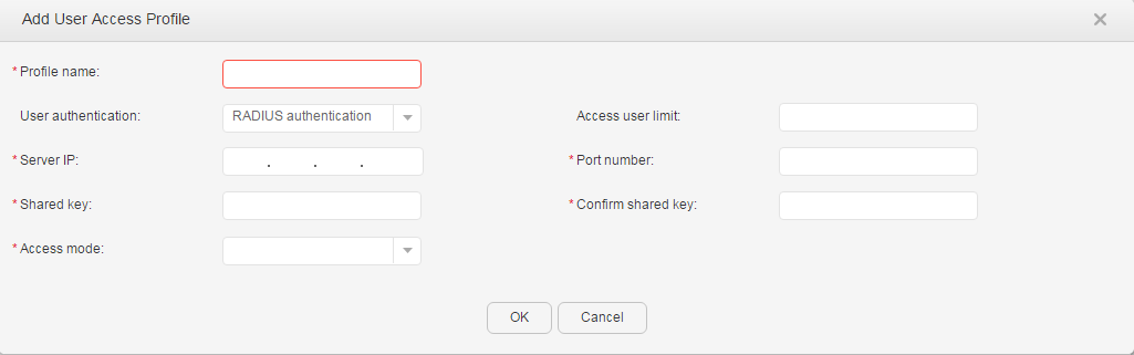
- Set User authentication to RADIUS authentication, as shown in Figure 7.
Table 6 describes the parameters on the page.
Table 6 Creating a user access profile: remote RADIUS authentication Item
Description
Profile name
Specifies the name of a user access control template.
Access user limit
Sets the maximum number of access users. The value ranges from 1 to 512.
Server IP
Specifies the IP address of a RADIUS authentication server.
Port number
Specifies the port number of the RADIUS authentication server.
The value is an integer that ranges from 1 to 65535.
Shared key
Specifies the RADIUS shared key.
The value is a string of 1 to 128 characters.
Confirm shared key
Configures the RADIUS shared key.
Access mode
Sets the user access authentication mode. You can select one or more from the following authentication modes:
- MAC: MAC address authentication
- 802.1X: 802.1X authentication
- Portal: Portal authentication
Portal Server
When Access mode includes Portal, the following parameters are valid:
Portal server name
Specifies the name of a Portal server template.
Source IP
Indicates the source IP address for the device to communicate with a Portal server.
URL
Sets a URL for a Portal server. The URL identifies the Portal server's website that can be visited by Portal authentication users.
Portal server IP
Configures an IP address for the Portal server.
NOTE:When S5720-HI, S5730-HI, S5731-H, S5731S-H, S5732-H, S6730-H, S6730S-H, and S6720-HI function as parent, you can specify multiple IP addresses for the portal server. For the operation method, see External Portal.
Port number
Configures a destination port number for the device to send packets to the Portal server.
The value is an integer that ranges from 1 to 65535.
Shared key
Configures a shared key used by the device to exchange information with the Portal server.
The value is a string of 1 to 16 characters.
Confirm shared key
Confirms the shared key used by the device to exchange information with the Portal server.
- Set User authentication to Non-authentication, as shown in Figure 5.
- Configure the parameters and click OK.
- Click Apply to complete the configuration.
- Set Connection type to Connect to PC, as shown in Figure 8.
- Select the network basic profile. The profile can be created in AS Profile Mgmt.
- Click next to Default VLAN. The Add VLAN and Gateway Configuration dialog box is displayed, as shown in Figure 3.
Table 2 describes the parameters in the Add VLAN and Gateway Configuration dialog box.
- Configure the parameters and click OK.
- Click next to Network Enhanced Profile. The Add Network Enhanced Profile dialog box is displayed, as shown in Figure 4.
Table 3 describes the parameters in the Add Network Enhanced Profile dialog box.
- Configure the parameters and click OK.
- Click next to User Access Profile. The Add User Access Profile dialog box is displayed, as shown in Figure 5, Figure 6, or Figure 7.
Table 4, Table 5, or Table 6 describes the parameters on the page.
- Configure the parameters and click OK.
- Click Apply to complete the configuration.
- Set Connection type to Connect to IP Phone, as shown in Figure 9.
- Select the network basic profile. The profile can be created in AS Profile Mgmt.
- Click next to Default VLAN. The Add VLAN and Gateway Configuration dialog box is displayed, as shown in Figure 3.
Table 2 describes the parameters in the Add VLAN and Gateway Configuration dialog box.
- Configure the parameters and click OK.
- Click next to Voice VLAN. The Add VLAN and Gateway Configuration dialog box is displayed, as shown in Figure 3.
Table 2 describes the parameters in the Add VLAN and Gateway Configuration dialog box.
- Configure the parameters and click OK.
- Click next to Network Enhanced Profile. The Add Network Enhanced Profile dialog box is displayed, as shown in Figure 4.
Table 3 describes the parameters in the Add Network Enhanced Profile dialog box.
- Configure the parameters and click OK.
- Click next to User Access Profile. The Add User Access Profile dialog box is displayed, as shown in Figure 5, Figure 6, or Figure 7.
Table 4, Table 5, or Table 6 describes the parameters on the page.
- Configure the parameters and click OK.
- Click Apply to complete the configuration.
- Set Connection type to User-defined, as shown in Figure 2.