Example for Configuring Unified Access for Wired and Wireless Users
Overview of Unified Access for Wired and Wireless Users
In practice, both wired and wireless users need to access one network. For example, the PCs and printers of a company connect to the network in wired mode, and laptops and mobile phones connect wirelessly. After unified access for wired and wireless users is configured on a network, users of both types can access the network and be managed in a unified manner.
Networking Requirements
A hospital needs to deploy both a wired and a wireless network. To simplify management and maintenance, the administrator requires that wired and wireless users be centrally managed on the AC, non-authentication and Portal authentication be configured for the wired and wireless users respectively, and wireless users roam under the same AC.
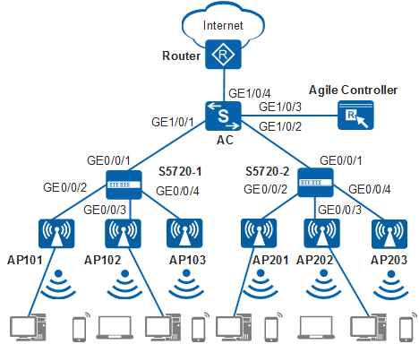
As shown in Figure 1, the AC connects to the egress gateway Router in the uplink direction. In the downlink direction, the AC connects to and manages APs through S5720-1 and S5720-2 access switches. The S5720-1 and S5720-2 are deployed in the first and second floors, respectively. An AP2010DN is deployed in each room to provide both wired and wireless access. The AP5030DN is deployed in the corridor to provide wireless network coverage. The S5720-1 and S5720-2 are PoE switches directly providing power to connected APs.
To facilitate network planning and management, the access switches are only used to transparently transmit data at Layer 2, and all gateways are configured on the AC
The AC functions as a DHCP server to assign IP addresses to APs, STAs, and PCs.
Data Planning
Item |
Interface |
VLAN |
Description |
|---|---|---|---|
AC |
GE1/0/1 |
100, 201 |
Connected to the S5720-1 |
GE1/0/2 |
100, 202 |
Connected to the S5720-2 |
|
GE1/0/3 |
200 |
Connected to the Agile Controller |
|
GE1/0/4 |
300 |
Connected to the egress gateway |
|
S5720-1 |
GE0/0/1 |
100, 201 |
Connected to the AC |
GE0/0/2 |
100, 201 |
Connected to AP101 |
|
GE0/0/3 |
100, 201 |
Connected to AP102 |
|
GE0/0/4 |
100, 201 |
Connected to AP103 |
|
S5720-2 |
GE0/0/1 |
100, 202 |
Connected to the AC |
GE0/0/2 |
100, 202 |
Connected to AP201 |
|
GE0/0/3 |
100, 202 |
Connected to AP202 |
|
GE0/0/4 |
100, 202 |
Connected to AP203 |
|
AP101 and AP102 |
Eth0/0/0 Eth0/0/1 GE0/0/0 |
201 |
GE0/0/0 connects to the S5720-1. Eth0/0/0 and Eth0/0/1 connects to wired users. AP101 and AP102 are AP2010DNs and are deployed in rooms on the first floor to provide wired and wireless access. |
AP103 |
GE0/0/0 |
201 |
GE0/0/0 connects to the S5720-1. AP103 is an AP5030DN and is deployed in the corridor on the first floor to provide wireless access. |
AP201 and AP202 |
Eth0/0/0 Eth0/0/1 GE0/0/0 |
202 |
GE0/0/0 connects to the S5720-2. Eth0/0/0 and Eth0/0/1 connects to wired users. AP201 and AP202 are AP2010DNs and are deployed in rooms on the second floor to provide wired and wireless access. |
AP203 |
GE0/0/0 |
202 |
GE0/0/0 connects to the S5720-2. AP203 is an AP5030DN and is deployed in the corridor on the second floor to provide wireless access. |
Item |
Data |
Description |
|---|---|---|
AC's source interface address |
10.23.100.1/24 |
- |
AP group |
|
- |
|
||
Portal access profile |
- |
|
Authentication profile |
- |
|
Regulatory domain profile |
|
- |
AP wired port profile |
Name: wired1, wired2, wired3, or wired4 |
- |
RRM profile |
Name: rrm1 |
- |
Radio profile |
- |
|
Security profile |
|
- |
SSID profile |
|
- |
Traffic profile |
Name: traffic1 |
- |
VAP profile |
|
Provides WLAN network coverage for the first floor of the building. |
|
Provides WLAN network coverage for the second floor of the building. |
|
DHCP server |
The AC functions as a DHCP server to assign IP addresses to APs, STAs, and PCs. |
- |
AP gateway and IP address pool range |
VLANIF 100: 10.23.100.1/24 10.23.100.2-10.23.100.254/24 |
- |
Gateway and IP address pool range of the wireless users |
VLANIF 101: 10.23.101.1/24 10.23.101.2-10.23.101.254/24 |
- |
VLANIF 102: 10.23.102.1/24 10.23.102.2-10.23.102.254/24 |
- |
|
Gateway and IP address pool range of the wired users |
VLANIF 201: 10.23.201.1/24 10.23.201.2-10.23.201.254/24 |
- |
VLANIF 202: 10.23.202.1/24 10.23.202.2-10.23.202.254/24 |
- |
|
Server parameters |
Authentication server:
|
|
Accounting server:
|
||
Authorization server:
|
||
Portal server:
|
Item |
Data |
Description |
|---|---|---|
AP101 |
Radio 0: channel 1 and power level 10 |
Use the WLAN Planner to plan AP installation locations, and the working channel and power of the AP radio. Set the channel mode and power mode to fixed, and configure the channel and power for each AP. |
AP102 |
Radio 0: channel 6 and power level 10 |
|
AP103 |
Radio 0: channel 11 and power level 10 Radio 1: channel 153 and power level 10 |
|
AP201 |
Radio 0: channel 1 and power level 10 |
|
AP202 |
Radio 0: channel 6 and power level 10 |
|
AP203 |
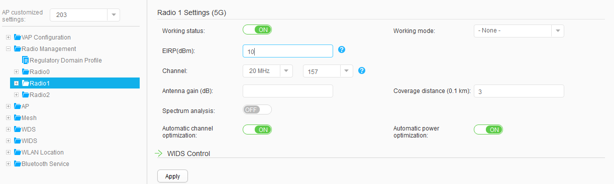
Radio 0: channel 11 and power level 10 Radio 1: channel 157 and power level 10 |
Configuration Roadmap
- Configure network interworking of the AC, APs, S5720-1, S5720-2, and other network devices.
- Configure the AC as a DHCP server to assign IP addresses to APs, wired users, and wireless users.
- Configure a RADIUS server template, configure authentication, accounting, and authorization in the template, and configure Portal authentication.
- Configure basic WLAN services, including AC system parameters, AP management, and WLAN service parameters.
- Configure VAPs and deliver VAP parameters to APs.
- Verify the configuration to ensure that both wired and wireless users can access the Internet.
Procedure
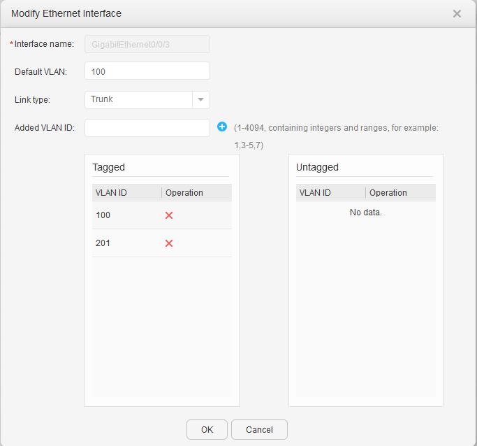
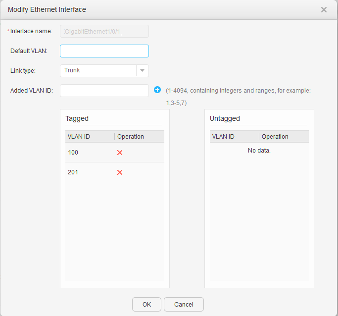
- Configure the VLANs to which interfaces of S5720-1 and S5720-2 belong.

The S5720-1 is used as an example here. The configuration on the S5720-2 is similar.
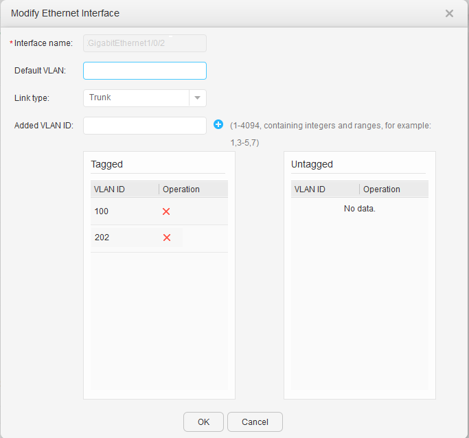
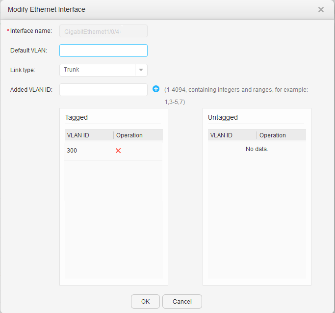
- Configure the VLANs to which interfaces of an AC belong.
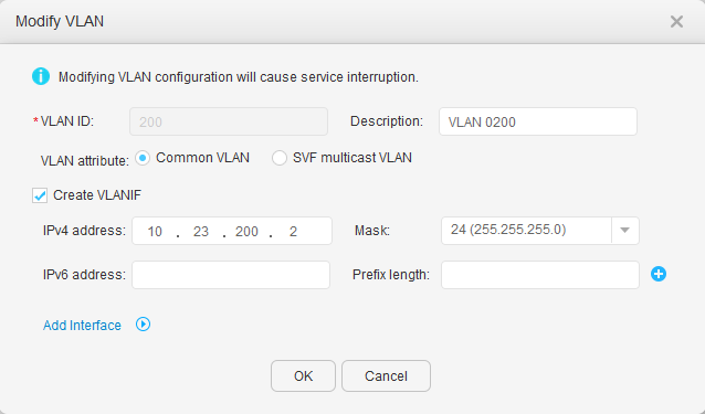
- Configure VLANIF 200 on the AC for communicating with the Agile Controller.
- Click 200 under VLAN ID. In the Modify VLAN dialog box, select Create VLANIF, and set IPv4 address and Mask, as shown in Figure 10. Click OK.
- Configure the AC as a DHCP server to assign IP addresses to PCs, APs, and STAs.
- Configure an IP address pool for the AC to assign IP addresses to APs.
- Choose to access the VLAN configuration page.
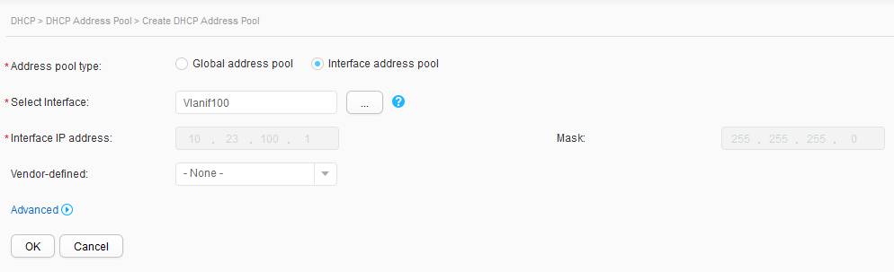
- Click 100 under VLAN ID. In the Modify VLAN dialog box, select Create VLANIF, and set IPv4 address and Mask, as shown in Figure 11. Click OK.
- Choose . Set DHCP status to ON to enable the DHCP function.
- Click Create. On the Create DHCP Address Pool page, set Address pool type to Interface address pool, select Vlanif100 for Select Interface, and click OK, as shown in Figure 12.
- Configure an IP address pool for the AC to assign IP addresses to STAs.
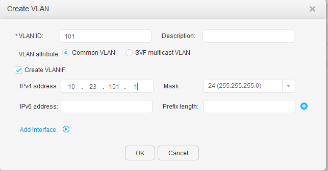
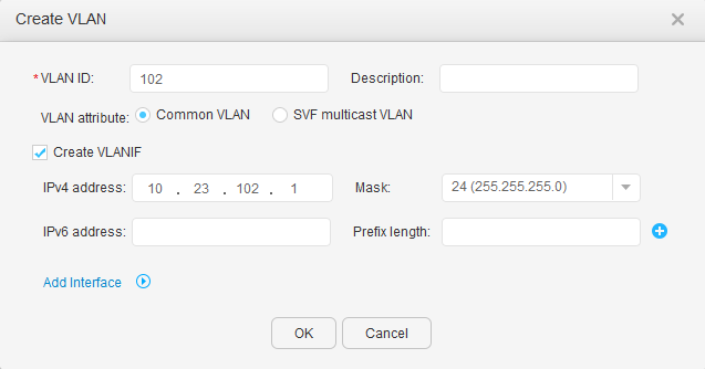
- Choose to access the VLAN configuration page.
- Click Create. In the Create VLAN dialog box, enter VLAN IDs in the VLAN ID text box, select Create VLANIF, and set IPv4 address and Mask, as shown in Figure 13 and Figure 14. Click OK.
- Choose . Set DHCP status to ON to enable the DHCP function.
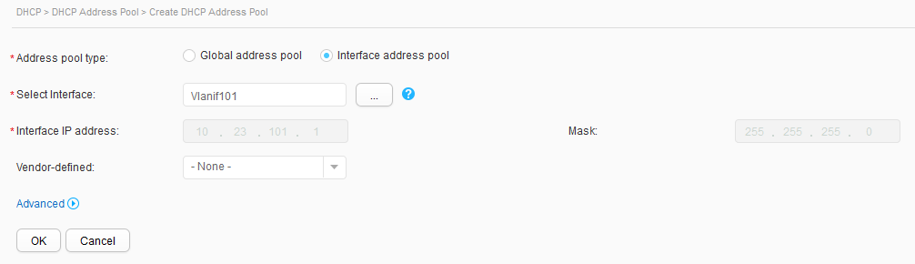
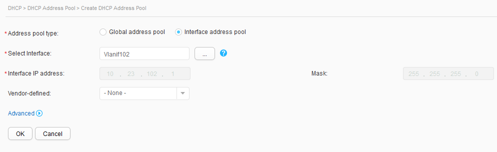
- Click Create. On the Create DHCP Address Pool page, set Address pool type to Interface address pool, select Vlanif101 for Select Interface, and click OK, as shown in Figure 15. Repeat the preceding operations for Vlanif102, as shown in Figure 16.
- Configure an IP address pool for the AC to assign IP addresses to PCs.
- Choose to access the VLAN configuration page.
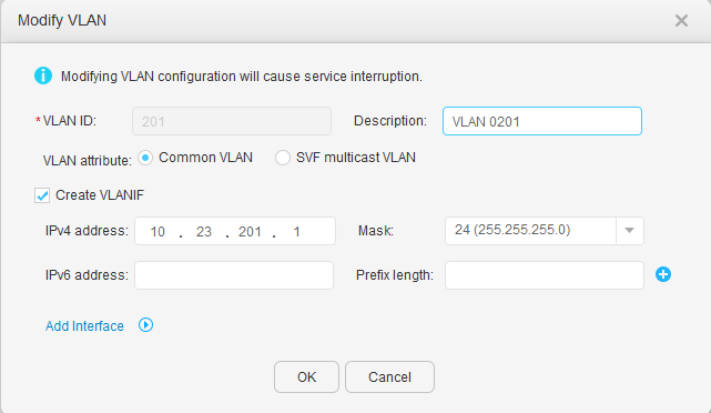
- Click 201 under VLAN ID. In the Modify VLAN dialog box, select Create VLANIF, and set IPv4 address and Mask, as shown in Figure 17 and Figure 18. Click OK.
- Choose . Set DHCP status to ON to enable the DHCP function.
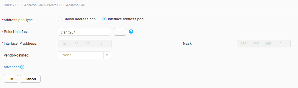
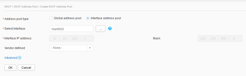
- Click Create. On the Create DHCP Address Pool page, set Address pool type to Interface address pool, select Vlanif201 for Select Interface, and click OK, as shown in Figure 19. Repeat the preceding operations for Vlanif202, as shown in Figure 20.
- Configure an IP address pool for the AC to assign IP addresses to APs.
- Configure a RADIUS server template, configure authentication, accounting, and authorization in the template, and configure Portal authentication on the AC.
- Configure a RADIUS server template, and configure authentication, accounting, and authorization in the template on the AC.
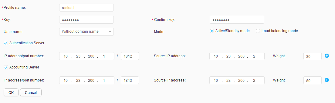
- Choose , click the RADIUS tab, and click Create. Create and configure RADIUS server template radius1, as shown in Figure 21. Click OK.
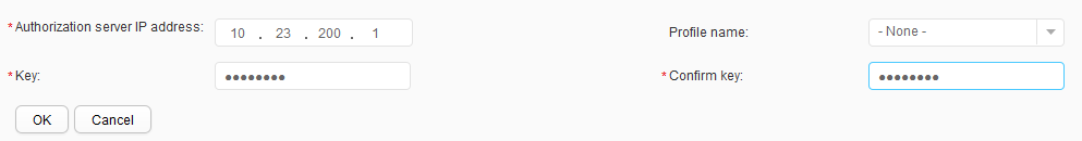
- Choose , click the RADIUS tab, and click Create to create and configure the authentication server, as shown in Figure 22. Click OK.
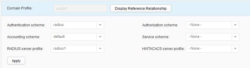
- Choose to access the Domain Profile List page. Click Create to access the Create Domain Profile page. Set Profile name to portal1, click OK, create the authentication domain portal1, and bind the RADIUS server template radius1 to the domain, as shown in Figure 23. Click Apply.
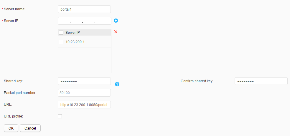
- Configure a Portal server.Choose , click the External Portal Server tab, and click Create to create and configure the Portal authentication server, as shown in Figure 24. Click OK.
- Enable Portal authentication for STAs. Non-authentication is adopted for wired users.
- Choose to access the Portal Profile List page. Click Create to access the Create Portal Profile page. Set Profile name to portal1 and click OK. On the Portal profile portal1 configuration page that is displayed, bind the Portal server portal1 to the Portal profile, and click Apply, as shown in Figure 25.
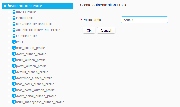
- Choose to access the Authentication Profile List page. Click Create to access the Create Authentication Profile page. Set Profile name to portal1 and click OK, as shown in Figure 26.
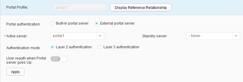
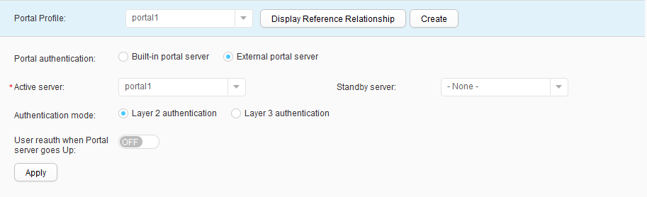
- Choose and select portal1 from the Portal Profile drop-down list box. Click Apply and bind the Portal profile portal1, as shown in Figure 27.
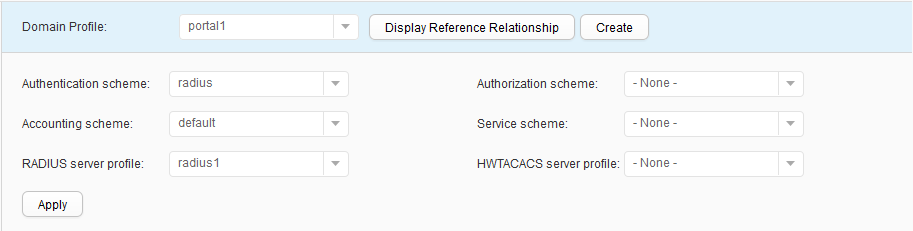
- Choose and select portal1 from the Domain Profile drop-down list box. Click Apply and bind the domain profile portal1, as shown in Figure 28.
- Configure a RADIUS server template, and configure authentication, accounting, and authorization in the template on the AC.
- Configure APs to go online.
- Create a regulatory domain profile, configure the AC's country code in the profile, and apply the profile to the AP group.
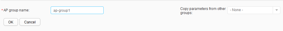
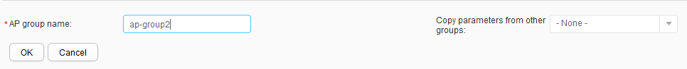
- Choose , click Create, and enter names in the AP group name text box, as shown in Figure 29. Click OK.
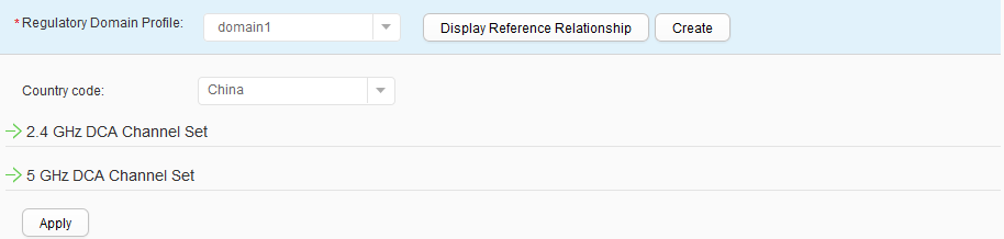
- Choose , and click ap-group1 to access the AP group configuration page. Choose , click Create, set Profile name to domain1 to create a regulatory domain profile, and bind the profile to the AP group ap-group1, as shown in Figure 30. Click Apply. Use the same method to bind the profile to ap-group2.
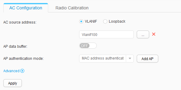
- Configure the source interface and authentication method.
Choose to access the AC Configuration page. Set AC source address to Vlanif100 and AP authentication mode to MAC address authentication, as shown in Figure 31. Click Apply.
- Import APs offline.
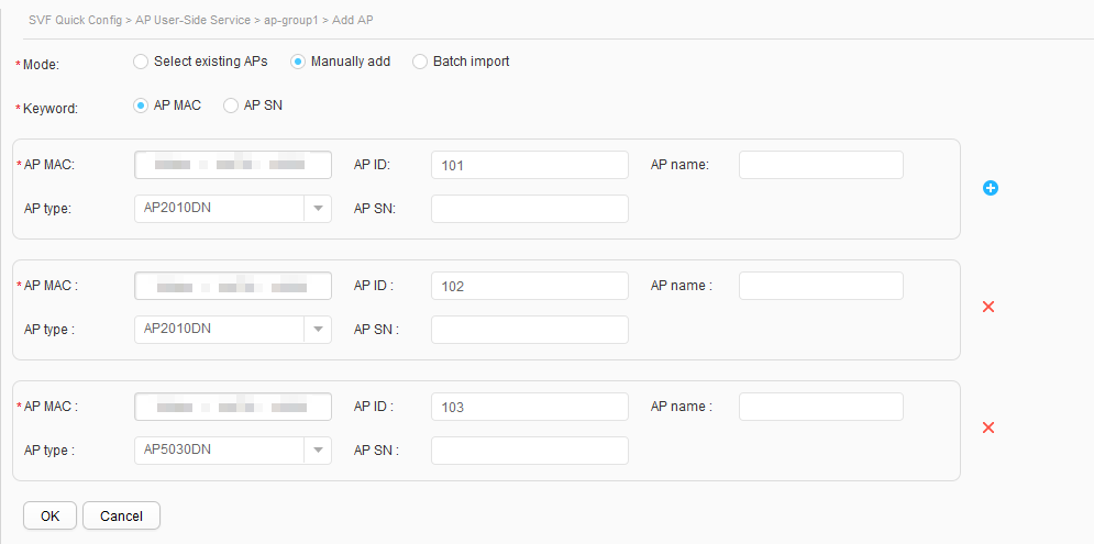
- Choose , and click ap-group1 in the AP group list. Click the AP Manage tab on the right, and click Add to access the page for adding APs.
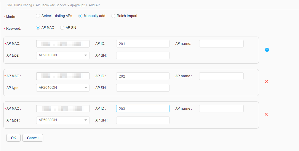
- Set Mode to Manually add, enter values in the AP MAC, AP ID, AP type text boxes, and click OK, as shown in Figure 32. Use the same method to add APs to ap-group2, as shown in Figure 33.
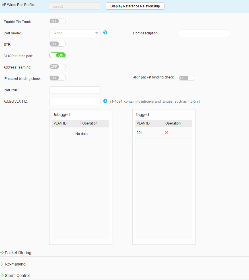
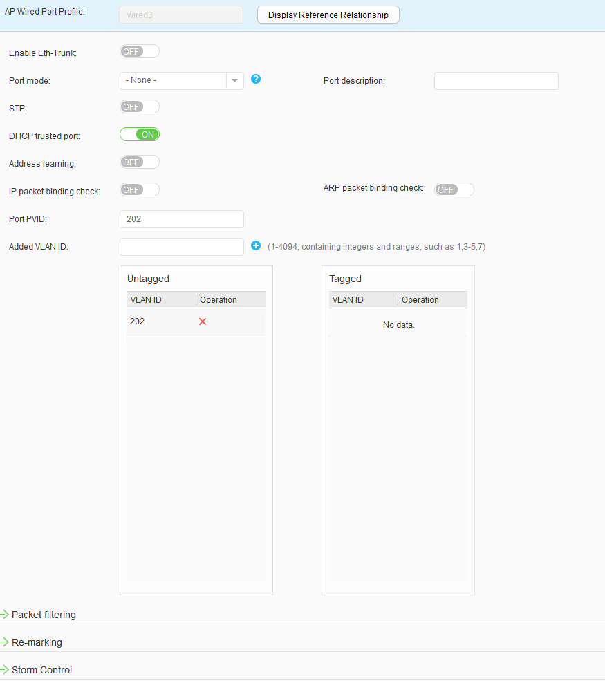
- Configure the uplink interface GE0/0/0, and downlink interfaces Eth0/0/0 and Eth0/0/1 on the AP2010DN to allow wired packets to pass.
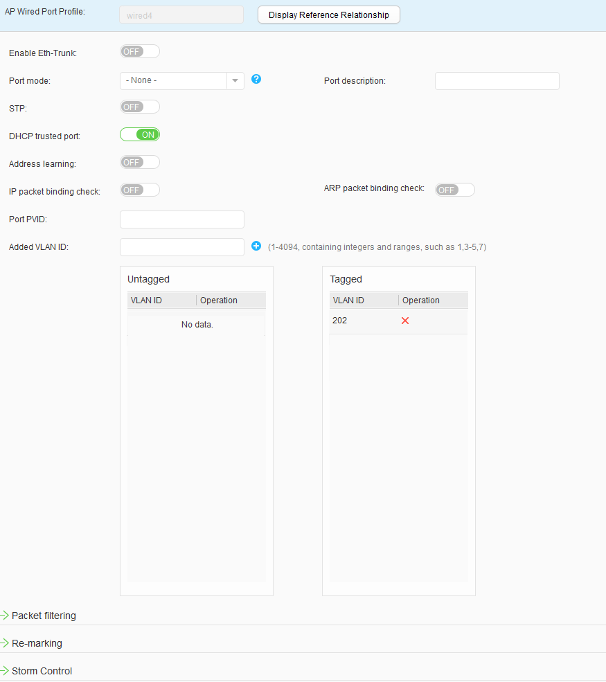
- Choose to access the AP Wired Port Profile List page. Click Create to access the Create AP Wired Port Profile page. Set Profile name to wired1 and click OK. Click the created AP wired interface profile, set parameters, and click Apply, as shown in Figure 34. Use the same method to configure wired2, wired3, and wired4, as shown in Figure 35, Figure 36, and Figure 37.
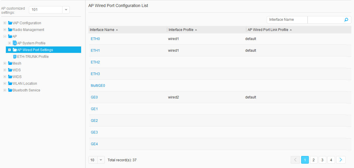
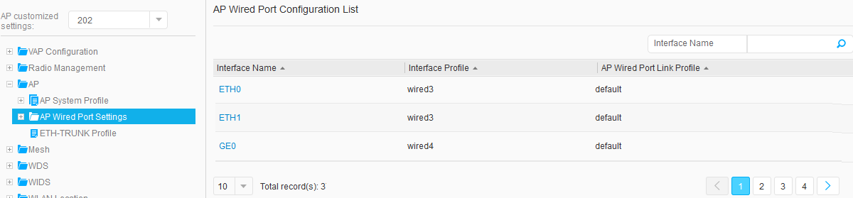
- Choose , and click an AP ID to access the AP Customized Settings page. Choose , click an interface in AP Wired Port Configuration List to access the page for binding an AP wired port profile. Select the wired port profile to bind and click OK. Figure 38, Figure 39, Figure 40, and Figure 41 show the configuration results.
- Create a regulatory domain profile, configure the AC's country code in the profile, and apply the profile to the AP group.
- Configure WLAN service parameters.
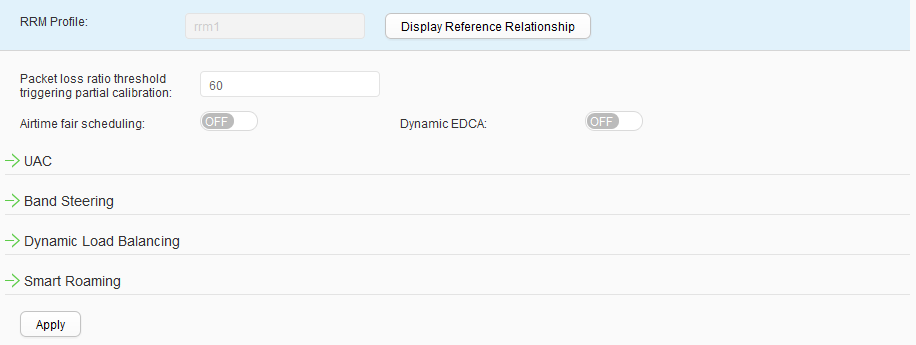
- Create an RRM profile rrm1.Choose to access the RRM Profile List page. Click Create to access the Create RRM Profile page. Set Profile name to rrm1 and click OK. On the RRM profile rrm1 configuration page that is displayed, click Apply, as shown in Figure 42.
- Create a radio profile and bind it to the RRM profile rrm1.
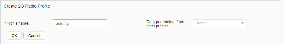
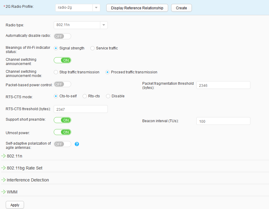
- Choose to access the 2G Radio Profile List page. Click Create to access the Create 2G Radio Profile page. Set Profile name to radio-2g and click OK, as shown in Figure 43.
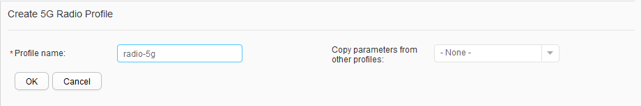
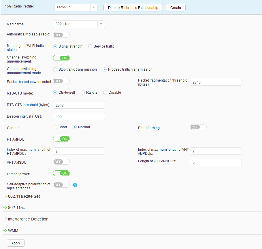
- Choose to access the 5G Radio Profile List page. Click Create to access the Create 5G Radio Profile page. Set Profile name to radio-5g and click OK, as shown in Figure 44.
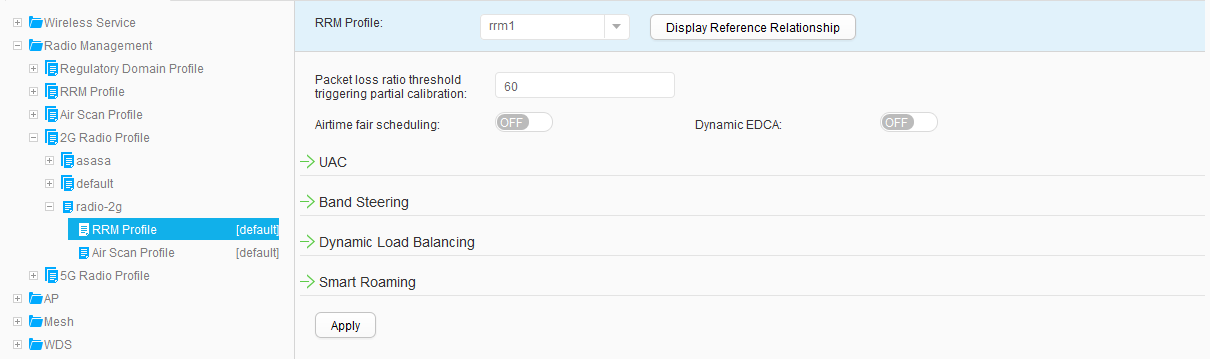
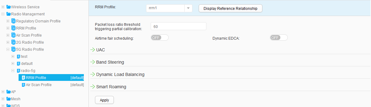
- Choose , and set RRM Profile to rrm1, as shown in Figure 45. Click Apply. Use the same method to bind the RRM profile rrm1 to the 5G radio profile radio-5g, as shown in Figure 46.
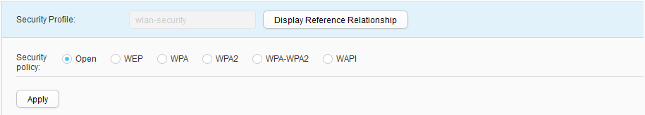
- Creating a security profileChoose , click Create, set Profile name to wlan-security, and configure this security profile, as shown in Figure 47. Click Apply.
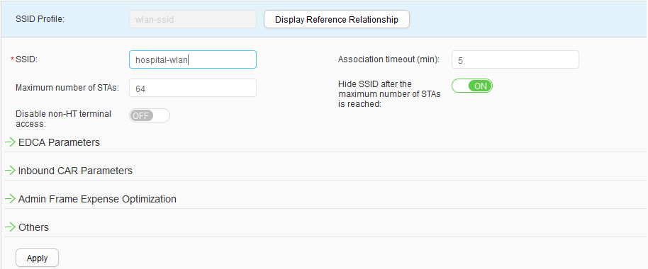
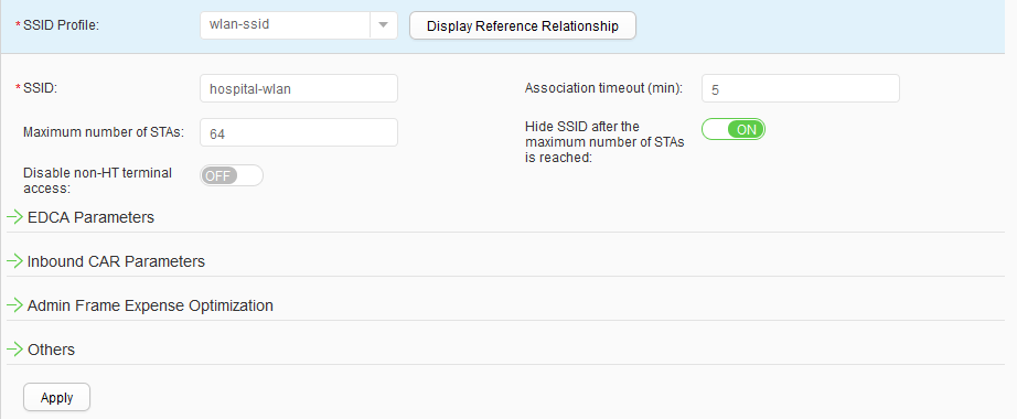
- Create an SSID profile.Choose , click Create, set Profile name to wlan-ssid, and configure this SSID profile, as shown in Figure 48. Click Apply.
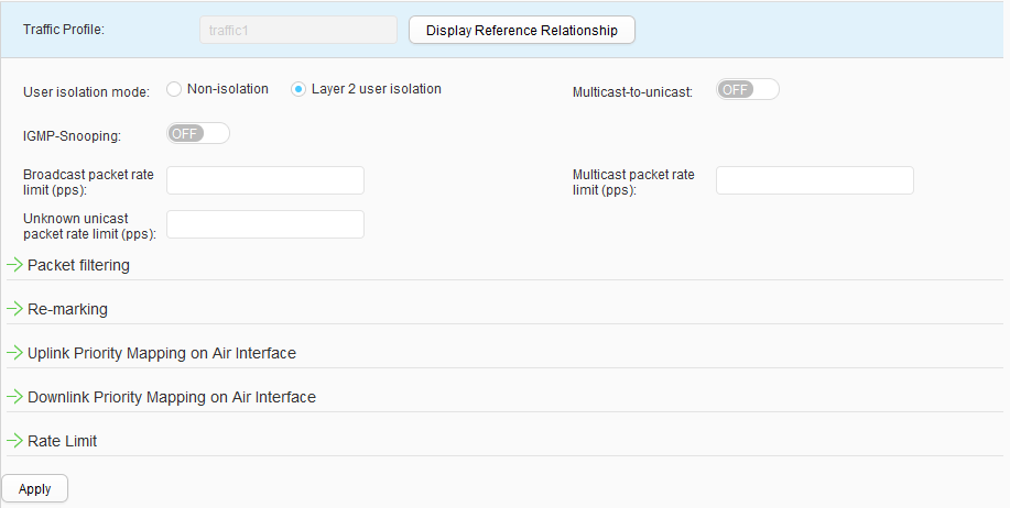
- Create a traffic profile.Choose , click Create, set Profile name to traffic1, and configure this traffic profile, as shown in Figure 49. Click Apply.
- Create a VAP profile.
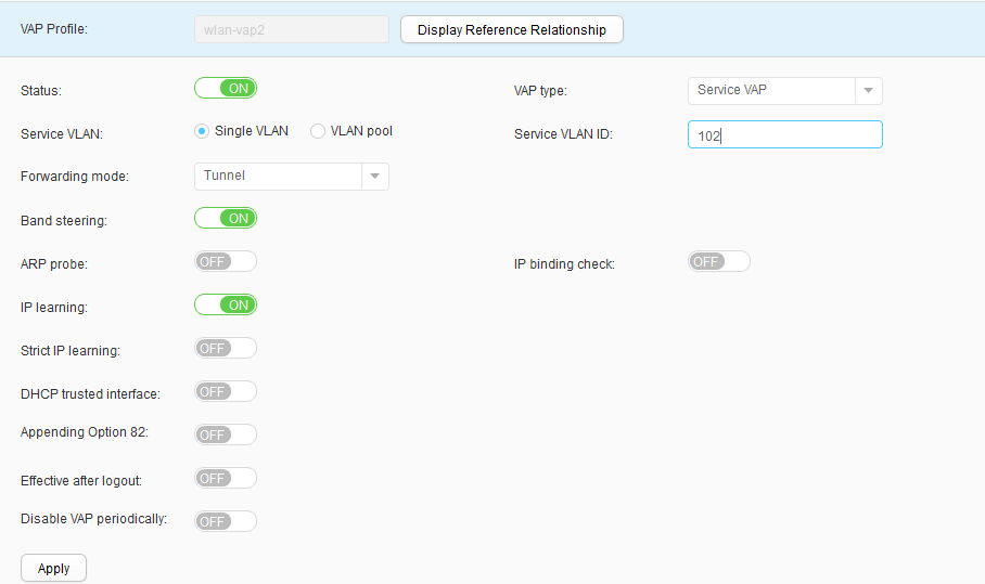
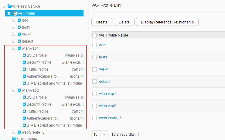
- Choose , click Create, set Profile name to wlan-vap1, and configure this VAP profile, as shown in Figure 50. Click Apply. Use the same method to create a VAP profile wlan-vap2, as shown in Figure 51.
- Choose , set SSID Profile to wlan-ssid, and click Apply, as shown in Figure 52. The SSID profile is bound successfully.
- Use the same method to bind the security profile, traffic profile, and authentication profile to VAP profiles, as shown in Figure 53.
- Bind VAP profiles and a radio profile to AP groups.
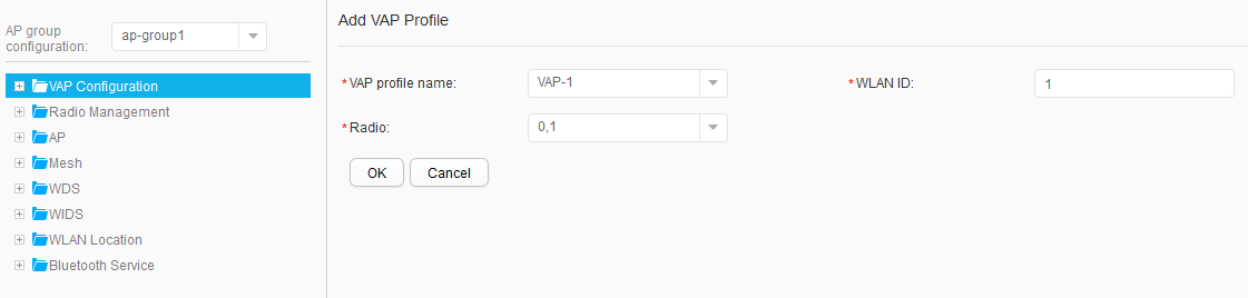
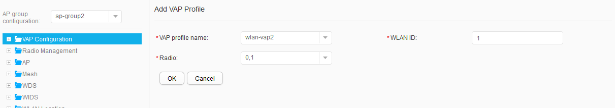
- Choose , and click ap-group1 to access the AP Customized Settings page. Click VAP Configuration, click Add on the right, set parameters, and click Apply, as shown in Figure 54. Use the same method to bind VAP profiles to ap-group2, as shown in Figure 55.
- Choose , and click ap-group1 to access the AP Customized Settings page. Choose , and select profiles in the 2G Radio Profile text box, as shown in Figure 56. Click Apply to complete the configuration of the 2G radio profile.
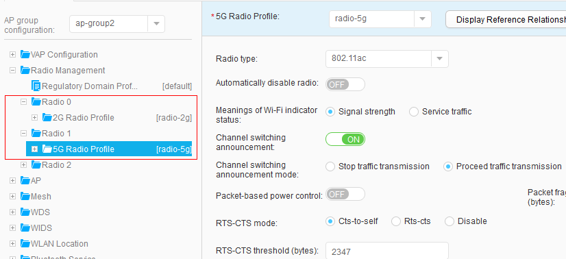
- Choose , and click ap-group1 to access the AP Customized Settings page. Choose , and select profiles in the 5G Radio Profile text box, as shown in Figure 57. Click Apply to complete the configuration of the 5G radio profile.
- Use the same method to bind 2G and 5G radio profiles to ap-group2, as shown in Figure 58.
- Create an RRM profile rrm1.
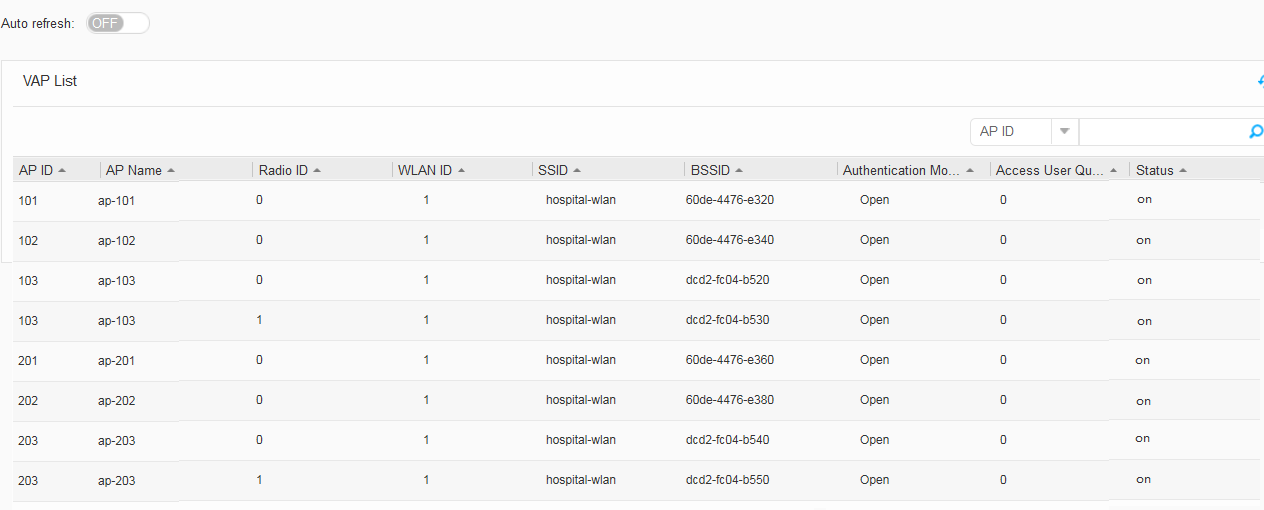
- Configure a VAP.


Operation Result
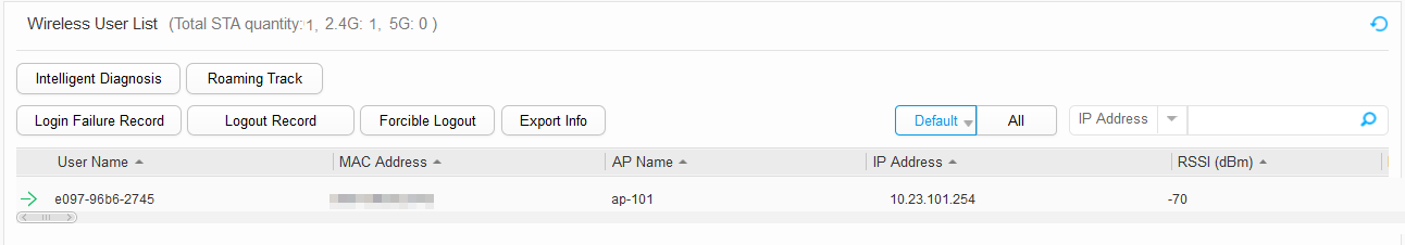
- When a STA detects and associates with the wireless network hospital-wlan successfully, the STA is assigned an IP address. Enter the password to access the wireless network. Choose , and view STA information, as shown in Figure 62.
- STAs and PCs obtain IP addresses and connect to the network properly.