Example for Configuring a Device as a DHCP Server (Based on an Interface Address Pool)
Networking Requirements
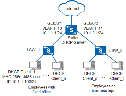
In Figure 1, an enterprise divides two network segments for office terminals: 10.1.1.0/24 for employees with fixed office terminals and 10.1.2.0/24 for employees on business trips to temporarily access the network. The enterprise requires that DHCP be used to assign IP addresses to employees with fixed office terminals and employees on business trips. A PC (DHCP Client_1) requires fixed IP address 10.1.1.100/24 to meet service requirements.
Configuration Roadmap
The configuration roadmap is as follows:
Configure the DHCP server function on the gateway device Switch to dynamically allocate IP addresses to terminals on the two network segments. PCs on the network segment 10.1.1.0/24 are employees' fixed office terminals, and the network segment 10.1.2.0/24 is used by travelling employees to access the network temporarily.

Configure interface link types and VLANs on LSW_1 and LSW_2 to implement Layer 2 communication.
Procedure
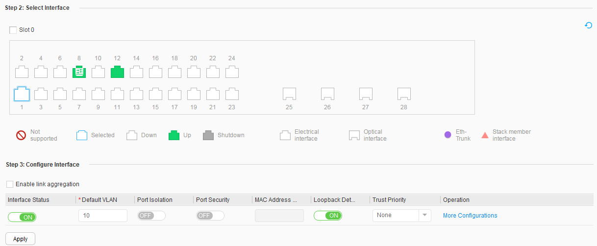
- Configure the VLANs to which interfaces belong.
- Select GE0/0/1 under Step 2: Select Interface, and set Interface Status and Default VLAN under Step 3: Configure Interface to ON and 10, as shown in Figure 2. You do not need to configure other parameters under Step 3: Configure Interface.
- Configure an IP address for each VLANIF interface.
- Click the VLAN data under VLAN ID to open the Modify VLAN page, select Create VLANIF, and set an appropriate address for IPv4 address, as shown in Figure 3.
- Configure an interface address pool.
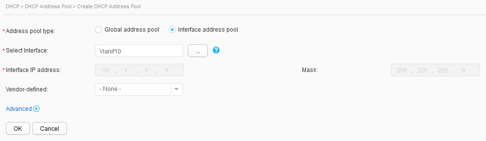
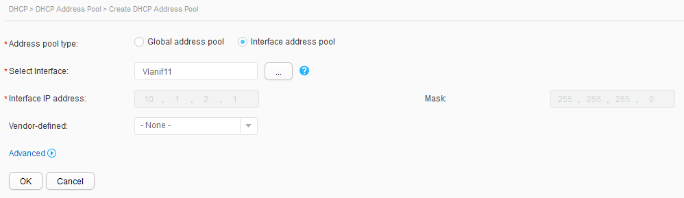
- Click Create. On the Create DHCP Address Pool page, set Address pool type to Interface address pool, select Vlanif10 for Select Interface, and click OK, as shown in Figure 4. Repeat the preceding operations to configure an address pool for VLANIF 11.
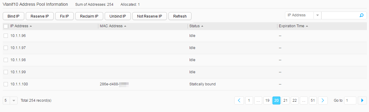
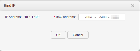
- In Address Pool List, select the check box of Vlanif10, and click Display Address Pool. On the Address Pool Information page, select the check box of 10.1.1.100, and click Bind IP. On the Bind IP page, enter 286e-d488-XXXX in the MAC address text box, and click OK, as shown in Figure 5.


Operation Result
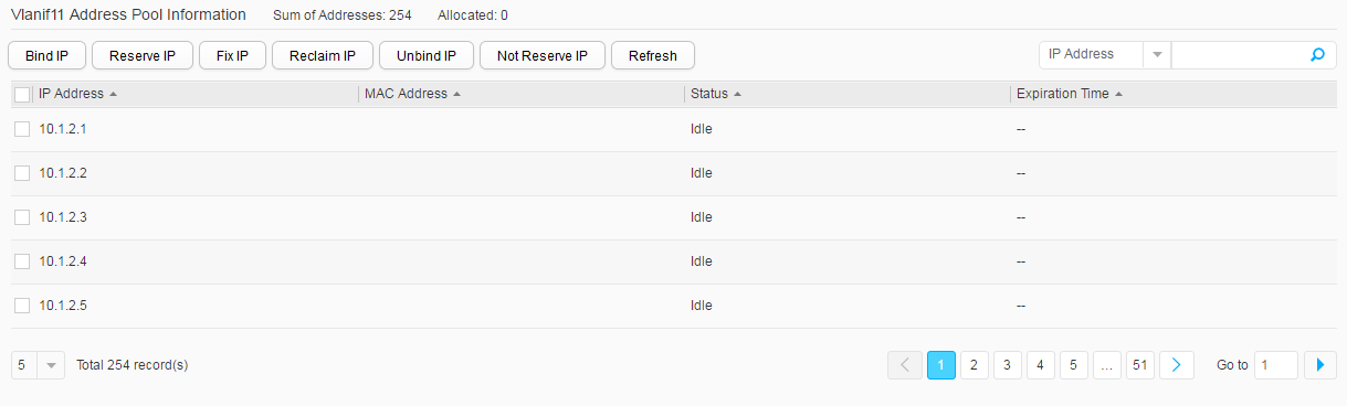
Choose and click the data lines of Vlanif10 and Vlanif11 in Address Pool List to view address allocation of interface address pools, as shown in Figure 6.