Example for Configuring IPSG Based on the DHCP Snooping Dynamic Binding Table to Prevent Hosts from Changing Their Own IP Addresses
Networking Requirements
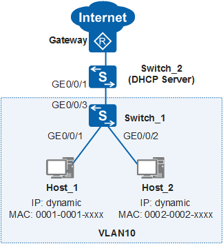
In Figure 1, hosts access the Internet through Switch_1, and Switch_2 functions as a DHCP server to allocate IP addresses to the hosts. The gateway is the egress device of the enterprise network. The administrator requires that the hosts use dynamically allocated IP addresses. The hosts cannot change their IP addresses to statically configured IP addresses to access the internet.
Configuration Roadmap
The requirement of the administrator can be met by configuring IPSG. The configuration roadmap is as follows:
- Configure the DHCP server (IP address pool 10.1.1.0/24) on Switch_2 to allocate IP addresses to hosts.
- Configure DHCP snooping on Switch_1. Hosts can then obtain IP addresses from the valid DHCP server, and the DHCP server can generate DHCP snooping dynamic binding entries. These entries record the bindings of IP addresses, MAC addresses, VLANs, and interfaces of hosts.
- Enable IPSG in the interfaces to which the hosts belong to prevent the hosts from accessing the internet with changed IP addresses.
Procedure
- Configure the DHCP server on Switch_2.
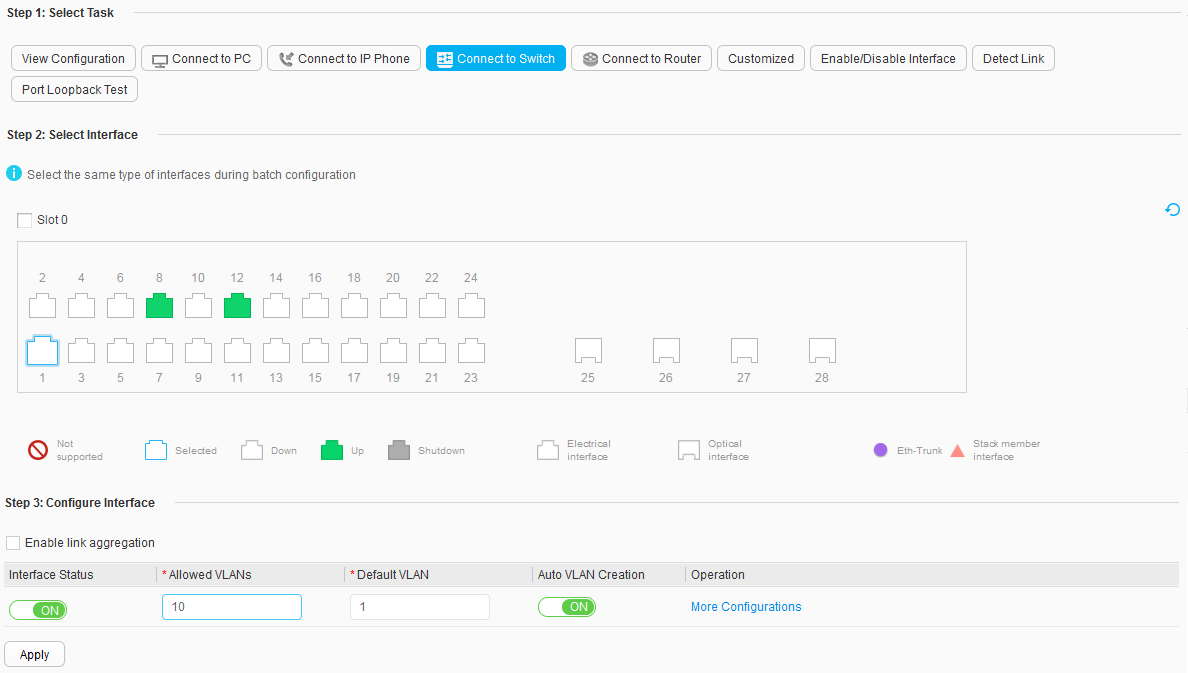
- Below Step 3: Configure Interface, set Interface Status to ON, Allowed VLANs to 10, and Auto VLAN Creation to ON, and retain the default values for other parameters, as shown in Figure 2. Click Apply. In the dialog box that is displayed, click OK.
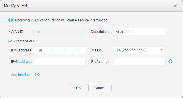
- Set VLAN ID to 10, set parameters according to the following configuration items, and retain the default values for other parameters, as shown in Figure 3. Click OK.
- Create VLANIF: select.
- IPv4 address: 10.1.1.1.
- Mask: 24 (255.255.255.0).
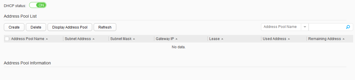
- Choose on the left. The DHCP Address Pool page is displayed. Set DHCP status to ON to enable the DHCP function, as shown in Figure 4.
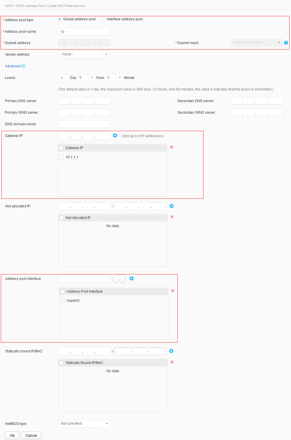
- Click Create. The Create DHCP Address Pool page is displayed. Set parameters according to the following configuration items, and retain the default values for other parameters, as shown in Figure 5. Click OK.
- Address pool type: Global address pool.
- Address pool name: 10.
- Subnet address: 10.1.1.0.
- Subnet mask: 24 (255.255.255.0).
- Gateway IP: 10.1.1.1.
- Address pool interface: Vlanif10.
- Configure DHCP snooping on Switch_1.
- Configure VLANs that interfaces belong to.
- Choose .
- Click Connect to Switch below Step 1: Select Task.
- Click GigabitEthernet 0/0/3 below Step 2: Select Interface.
- Below Step 3: Configure Interface, set Interface Status to ON, Allowed VLANs to 10, and Auto VLAN Creation to ON, and retain the default values for other parameters, as shown in Figure 6. Click Apply. In the dialog box that is displayed, click OK.
- Choose .
- Click Connect to PC below Step 1: Select Task.
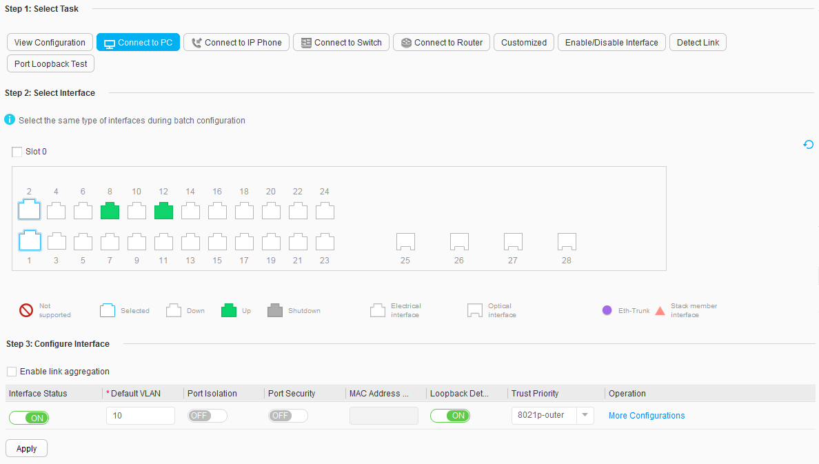
- Click GigabitEthernet 0/0/1 and GigabitEthernet 0/0/2 below Step 2: Select Interface
- Below Step 3: Configure Interface, set Interface Status to ON and Default VLANto 10, and retain the default values for other parameters, as shown in Figure 7. Click Apply. In the dialog box that is displayed, click OK.
- Enable DHCP snooping and configure GigabitEthernet 0/0/3 connected to the DHCP server as a trusted interface.
- Choose . The DHCP Address Pool page is displayed. Set DHCP status to ON to enable the DHCP function, as shown in Figure 8.
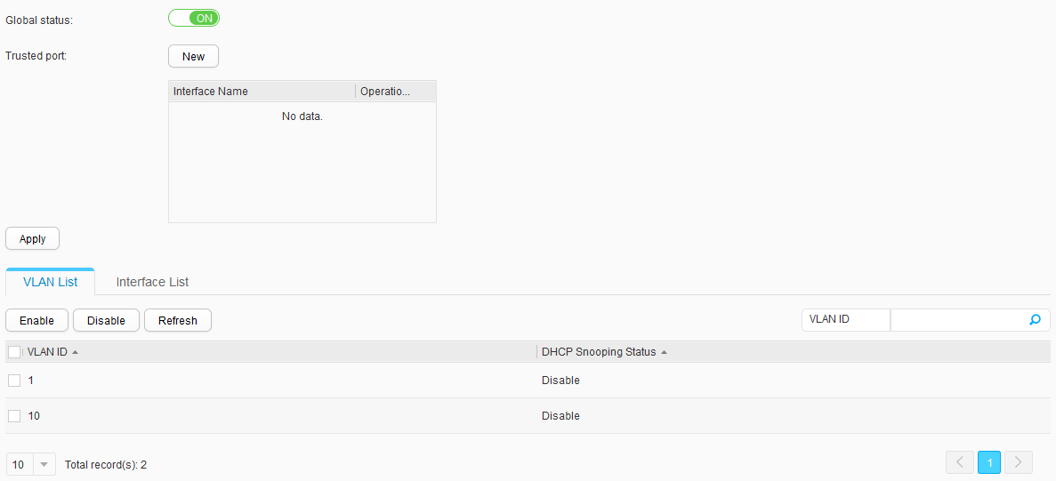
- Choose . Set Global status to ON to enable the DHCP snooping function, as shown in Figure 9.
- Click New next to Trusted port. In the displayed dialog box, click GigabitEthernet 0/0/3. Click Apply.
- Select VLAN 10 in VLAN List and click Enable. In the dialog box that is displayed, click OK to enable DHCP snooping in VLAN 10.
- Configure VLANs that interfaces belong to.
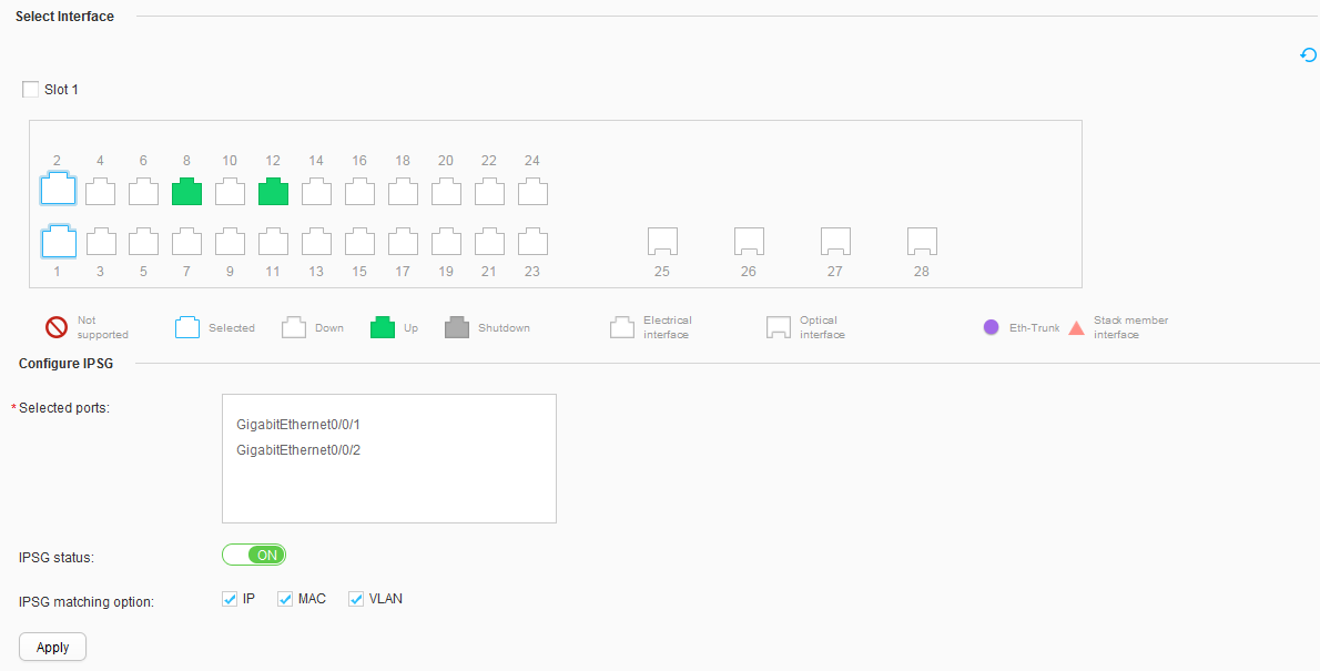
- Enable IPSG on an interface of Switch_1.
- Click GigabitEthernet 0/0/1 and GigabitEthernet 0/0/2 below Select Interface. Set IPSG status to ON, as shown in Figure 10.

Operation Result
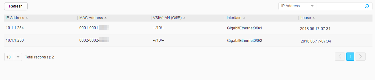
After the host goes online, choose to view dynamic binding entries, as shown in Figure 11.