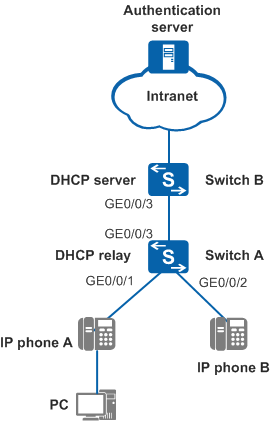
Example for Connecting IP Phones to Switches Through LLDP
Networking Requirements
- The priority of voice packets sent by IP phones is low and needs to be increased to ensure communication quality.
- Voice and data packets are transmitted in VLAN 100 and VLAN 101, respectively.
- IP addresses of IP phones are dynamically allocated by the DHCP server, and the IP addresses of IP phones and the DHCP server are located on different network segments.
- IP phones need to connect to switches through MAC address authentication.
Configuration Roadmap
The configuration roadmap is as follows:
- Enable LLDP on SwitchA.
- Configure SwitchA to forward data flows and enable the voice VLAN function.
- Configure the DHCP relay function on SwitchA.
- Configure SwitchB as the DHCP server to allocate IP addresses to IP phones.
- Configure AAA on SwitchA.
- Configure MAC address authentication on SwitchA to authenticate IP phones.
- Configure the Agile Controller-Campus or iMaster NCE-Campus.
Procedure
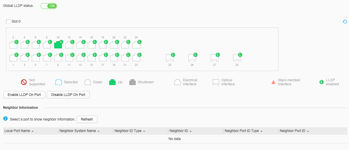
- Enable LLDP on SwitchA.
- Set Global LLDP status to ON to enable global LLDP, as shown in Figure 2.
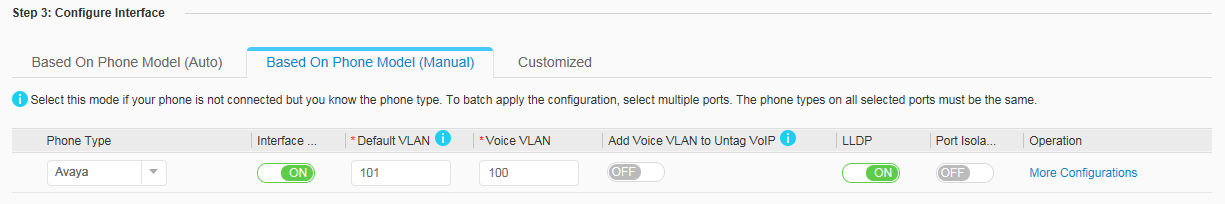
- Configure SwitchA to forward data flows and enable the voice VLAN function.
- Select GE0/0/1 and GE0/0/2 on the device panel, set parameters according to Figure 3 in Step3: Configure Interface, and click Apply. In the dialog box that is displayed, click OK.
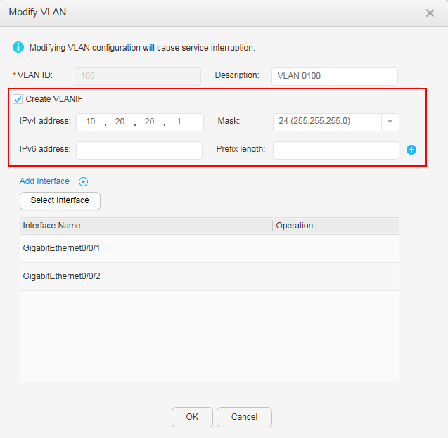
- Configure the DHCP relay function on SwitchA.
- Choose to access the VLAN configuration page. Click VLAN data under VLAN ID to access the Modify VLAN page, set parameters according to Figure 4, and click OK.
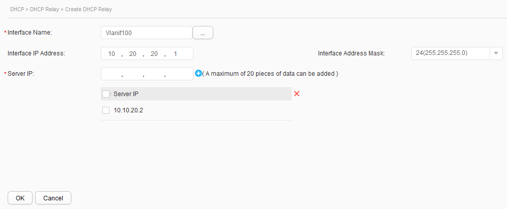
- Choose . Click Create. On the Create DHCP Relay page, configure a DHCP relay for a VLANIF interface, and click OK, as shown in Figure 5.
- Choose to access the VLAN configuration page. Click Create, set parameters according to Figure 6, and click OK. VLANIF 200 is created and the uplink interface is added to VLAN 200.
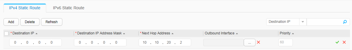
- Choose , click Add, set parameters according to Figure 7, and click
 to complete static route configuration on SwitchA. The next-hop address of the route is the IP address of VLANIF 200 on SwitchB.
- Configure SwitchB as the DHCP server to allocate IP addresses to IP phones.
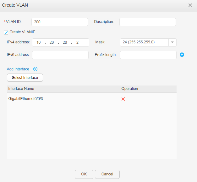
- Choose to access the VLAN configuration page. Click Create, set parameters according to Figure 8, and click OK. VLANIF 200 is created and the uplink interface is added to VLAN 200.
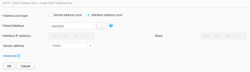
- Click Create. On the Create DHCP Address Pool page, configure the DHCP server for a VLANIF interface, and click OK, as shown in Figure 9.
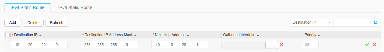
- Choose , click Add, set parameters according to Figure 10, and click to complete static route configuration on SwitchB. The next-hop address of the route is the IP address of VLANIF 200 on SwitchA.
- Configure AAA on SwitchA.
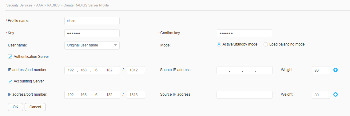
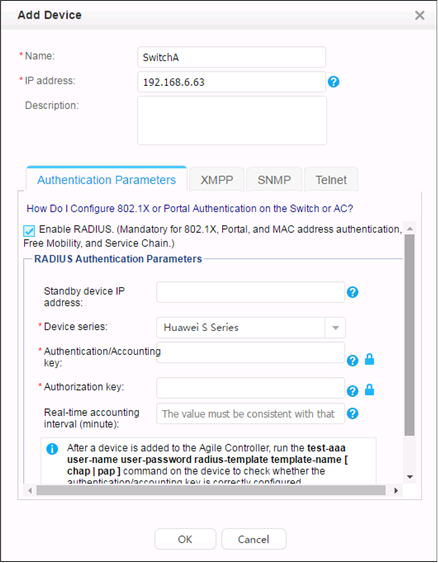
- Choose , select RADIUS, and click Create to create and configure the RADIUS server template cisco, as shown in Figure 11. Click OK.
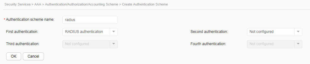
- Click Authentication/Authorization/Accounting Scheme and click Create to create an authentication scheme radius and set the authentication mode to RADIUS, as shown in Figure 12. Click OK.
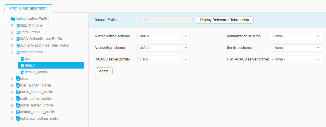
- Choose to access the Domain Profile List page. Click default under Domain Profile List to access the domain profile configuration page. Bind the AAA authentication scheme radius and RADIUS server template cisco to the domain profile, as shown in Figure 13. Click Apply.
- Configure MAC address authentication on SwitchA to authenticate IP phones.
- Run the authentication unified-mode command in the system view to configure the NAC unified mode.

By default, the unified mode is used. The switch restarts after the NAC mode is changed between the common mode and unified mode. After the configuration is complete, save the configuration
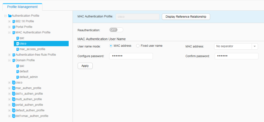
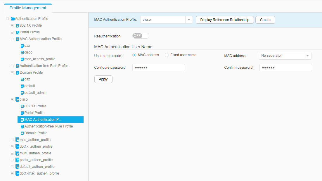
- Choose to access the MAC Authentication Profile List page. Click Create. The Create MAC Authentication Profile page is displayed. Set Profile name to cisco and click OK to access the MAC access profile parameter configuration page, as shown in Figure 14. Click Apply.
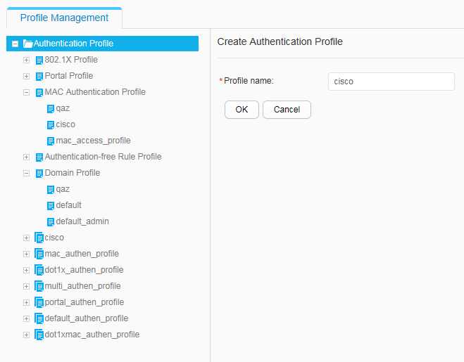
- Choose to access the Authentication Profile List page. Click Create and set Profile name to cisco, as shown in Figure 15. Click OK to create an authentication profile cisco.
- Choose . Select cisco from the MAC Authentication Profile drop-down list box, as shown in Figure 16. Click Apply to bind the MAC access profile cisco to the authentication profile cisco.
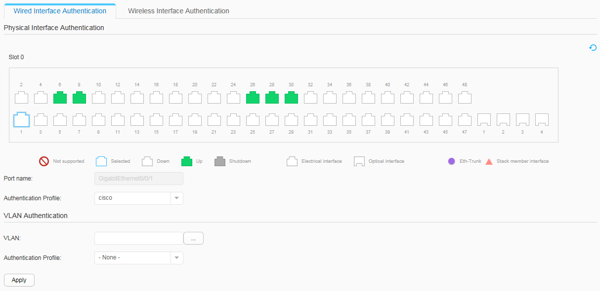
- Choose , select GE0/0/1 on the device panel, and set Authentication Profile to cisco, as shown in Figure 17. Click Apply. Configure GE0/0/2 in the same manner.
- Run the authentication unified-mode command in the system view to configure the NAC unified mode.
- Configure the Agile Controller-Campus or iMaster NCE-Campus. The display of the Agile Controller-Campus or iMaster NCE-Campus varies depending on versions. V100R002C10SPC401 is used as an example.
- Log in to the Agile Controller-Campus or iMaster NCE-Campus.
Open the Internet Explorer, enter the Agile Controller-Campus or iMaster NCE-Campus access address in the address bar, and press Enter.
Enter the administrator user name and password. If you log in to the Agile Controller-Campus or iMaster NCE-Campus for the first time, use the super administrator user name admin and password Changeme123. Change the password immediately after logging in. Otherwise, the Agile Controller-Campus or iMaster NCE-Campus cannot be used.
The following access modes of the Agile Controller-Campus or iMaster NCE-Campus can be used.Access Mode
Description
https:// Agile Controller-Campus or iMaster NCE-Campus-IP:8443
Agile Controller-Campus or iMaster NCE-Campus specifies the IP address of the Agile Controller-Campus or iMaster NCE-Campus.
IP address of the Agile Controller-Campus or iMaster NCE-Campus
If port 80 is enabled during installation, you can access the Agile Controller by entering its IP address without the port number. The URL of the Agile Controller-Campus or iMaster NCE-Campus will automatically change to https://Agile Controller-IP:8443.
- Add a MAC address.
- Choose .
- Select All Accounts.
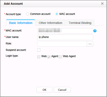
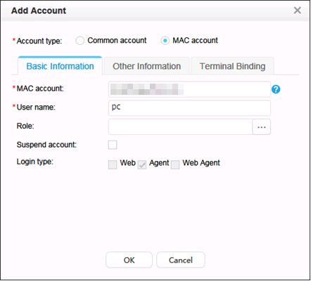
- Click Add to create a MAC account. The value of the first MAC Account parameter is the IP phone's MAC address, and the value of the second MAC Account parameter is the PC's MAC address.
- Add SwitchA to the Agile Controller-Campus or iMaster NCE-Campus.
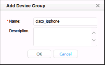
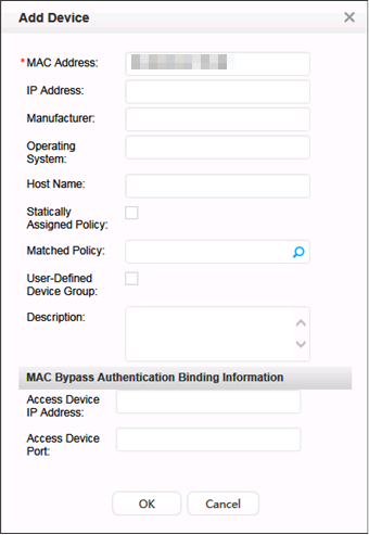
- Add an IP phone to the Agile Controller-Campus or iMaster NCE-Campus.
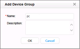
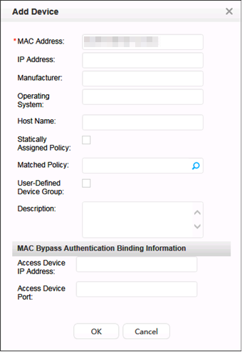
- Add a PC to the Agile Controller-Campus or iMaster NCE-Campus.
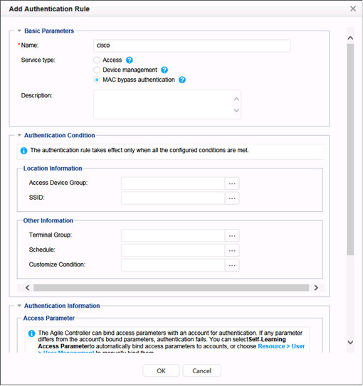
- Add an authentication rule.
Choose and click Add to create authentication rules for the IP phone and PC respectively.

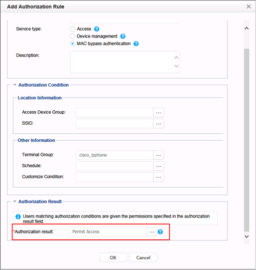
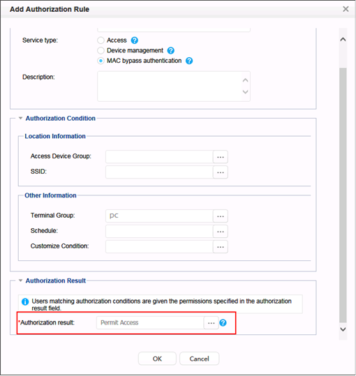
- Add an authorization result.
Choose and click Add to create authorization rules for the IP phone and PC respectively.
- Log in to the Agile Controller-Campus or iMaster NCE-Campus.