< Home

Wireless Service

Context

You can create an SSID and add a VAP to and delete a VAP from an AP group.

Procedure

  • Create an SSID.
    1. Choose Configuration > Fast WLAN Config > Wireless Service. The Wireless Service Configuration page is displayed, as shown in Figure 1.

      Figure 1 Wireless Service page

    2. Click Create. The Create User page is displayed, as shown in Figure 2.

      Figure 2 Creating an SSID

      Configure parameters according to Table 1.

      Table 1 Parameters for creating an SSID

      Parameter

      Description

      SSID Name

      Name of an SSID to be created.

      Forwarding mode

      Service forwarding mode.

      Service VLAN

      Service VLAN of a VAP.
      • When a specific VLAN is configured as the service VLAN of a VAP, STAs connected to the VAP join the same VLAN.
      • When VLANs in a VLAN pool are configured as service VLANs of a VAP, STAs connected to the VAP join different VLANs.

      Service VLAN ID

      ID of the service VLAN.

      This parameter can be configured only when Service VLAN is set to Single VLAN.

      VLAN Pool

      VLAN pool used for service VLANs.

      Click Create and set parameters according to VLAN Pool.

      This parameter can be configured only when Service VLAN is set to VLAN Pool.

    3. After basic information about the SSID is configured, click Next. The 2. Security Authentication page is displayed, as shown in Figure 3.

      Figure 3 Security Authentication page

      • Non-authentication: Wireless devices can connect to a network without authentication.

        Set Security settings to Open (applicable to personal networks).

        This authentication mode brings security risks. You are advised to use other authentication modes.

      • Key authentication: Wireless devices can access the network when the correct keys are entered.

        Set Security settings to Key (applicable to personal networks), set the corresponding algorithm, and configure a key.

        The TKIP algorithm brings security risks. You are advised to use the AES algorithm.

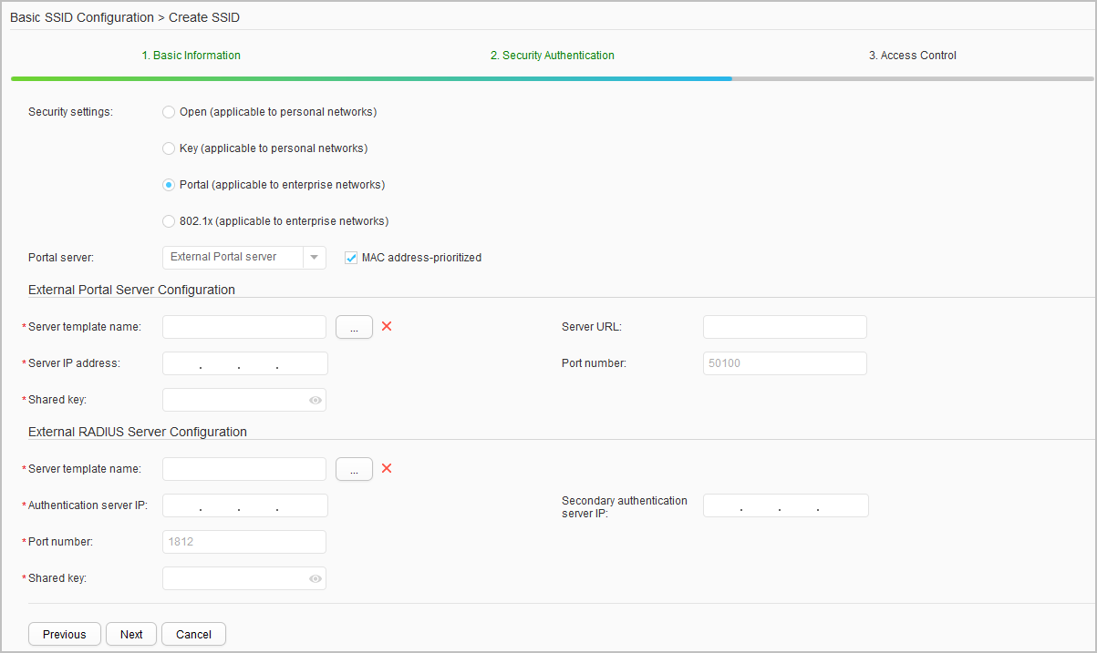
      • Portal authentication: No specific client is required in this authentication mode. The Portal server provides users with free Portal services and a Portal authentication page.
        1. Set Security settings to Portal (applicable to enterprise networks). The Portal authentication configuration area is displayed, as shown in Figure 4.
          Figure 4 Portal authentication configuration

        2. Configure parameters according to Table 2.
          Table 2 Portal authentication parameters

          Parameter

          Description

          Portal server

          Type of the Portal server, which can be a built-in Portal server or an external Portal server.

          MAC address-prioritized

          Whether to enable MAC address-prioritized Portal authentication.

          After passing Portal authentication, STAs may be disconnected from a wireless network frequently when they move from one wireless signal coverage area to another or when wireless signals are unstable. MAC address-prioritized Portal authentication allows these STAs to access the WLAN again, without the need to enter the user name and password.

          This parameter can be configured only when Portal server is set to External Portal server.

          External RADIUS authentication

          Whether to enable external RADIUS authentication.

          This parameter can be configured only when Portal server is set to Built-in Portal Server Configuration.

          External Portal Server Configuration

          This parameter can be configured only when Portal server is set to External Portal server.

          Server template name

          Name of an external Portal server.

          Server URL

          URL of an external Portal server.

          Server IP address

          IP address of an external Portal server.

          Port number

          Destination port number for the device to send packets to the Portal server.

          Shared key

          Shared key used by the device and external Portal server to exchange information.

          Built-in Portal Server Configuration

          This parameter can be configured only when Portal server is set to Built-in Portal server.

          Server IP address

          IP address of the built-in Portal server.

          Port number

          Port number for the built-in Portal server to provide authentication services.

          SSL policy

          SSL policy used by the built-in Portal server.

          Local user

          User name and password used to access a WLAN.

          External RADIUS Server Configuration

          Server template name

          Name of a RADIUS authentication server.

          Authentication server IP

          IP address of a RADIUS authentication server.

          Secondary authentication server IP

          IP address of a secondary RADIUS authentication server.

          Port number

          Port number of a RADIUS authentication server.

          Shared key

          Shared key used by the device and RADIUS authentication server to exchange information.

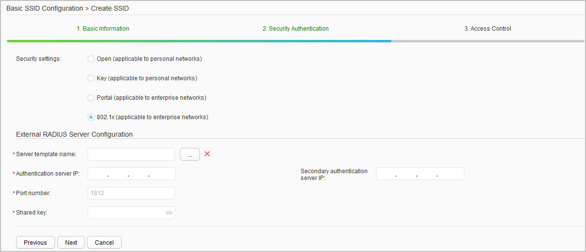
      • 802.1X authentication: You can configure 802.1X authentication to implement interface-based network access control, that is, to authenticate and control users connected to an interface of an access control device.
        1. Set Security settings to 802.1x (applicable to enterprise networks). The 802.1X authentication configuration area is displayed, as shown in Figure 5.
          Figure 5 802.1X authentication configuration

        2. Configure parameters according to Table 2.

    4. After the security authentication configuration is complete, click Next. The 3. Access Control page is displayed, as shown in Figure 6.

      Figure 6 Access control

      Configure parameters according to Table 3.

      Table 3 Access Control page

      Parameter

      Description

      Binding the AP group

      AP group to which a VAP profile is bound.

      WLAN ID configuration

      ID of a VAP profile.

      Valid radio

      Radio to which a VAP profile is applied.

      • Radio 0: 2.4 GHz
      • Radio 1: 5 GHz
      • Radio 2: 5 GHz

      Single-user rate limit (Kbps)

      Rate limit for upstream and downstream traffic on a specified STA associated with a VAP.

    5. Click Finish.
  • Modify an SSID.

    1. Choose Configuration > Fast WLAN Config > Wireless Service. The Wireless Service Configuration page is displayed, as shown in Figure 1.
    2. Select the SSID to modify. The page for modifying the SSID is displayed.
    3. Modify parameters according to Table 1, Table 2, and Table 3.
    4. Click Finish.

  • Add an SSID.

    1. Choose Configuration > Fast WLAN Config > Wireless Service. The Wireless Service Configuration page is displayed, as shown in Figure 1.
    2. Click Add. The Add SSID page is displayed, as shown in Figure 7.
      Figure 7 Add SSID page

    3. Select an SSID and set other parameters according to Table 3.
    4. Click OK.

  • Remove an SSID.

    1. Choose Configuration > Fast WLAN Config > Wireless Service. The Wireless Service Configuration page is displayed, as shown in Figure 1.
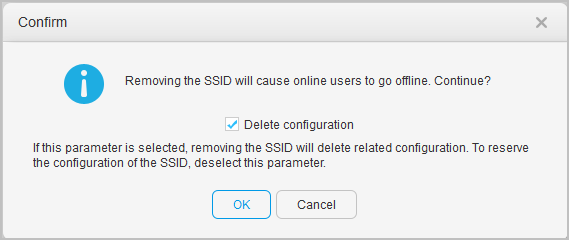
    2. Select an SSID to remove and click Remove. The Confirm dialog box is displayed, as shown in Figure 8.
      Figure 8 Confirm dialog box

    3. Click OK. The SSID bound to the AP group is removed and the SSID configuration is deleted.

      To remove an SSID bound to the AP group and retain the SSID configuration, deselect Delete configuration.

  • View information about the AP group bound to an SSID.

    1. Choose Configuration > Fast WLAN Config > Wireless Service. The Wireless Service Configuration page is displayed, as shown in Figure 1.
    2. Click View to view information about the AP group bound to the SSID.

Copyright © Huawei Technologies Co., Ltd.
< Previous topic Next topic >