Using Front Mounting Brackets
Context
This installation method applies to the following switches:
- All S2700 series switches
- All S3700 series switches
- Some S5700 models, including S5700-LI, S5700S-LI, S5710-LI, S5720-LI, S5720S-LI, S5700-SI, S5720-SI (except 420-mm deep models), S5720S-SI, S5700-EI, S5720-EI (except 420-mm deep models), S5700-HI, S5720I-12X-SI-AC, S5720I-12X-PWH-SI-DC, S5720I-28X-SI-AC, S5720I-28X-PWH-SI-AC, S5735-L (except 420-mm deep models), S5735S-L (except 420-mm deep models), and S5735S-L-M
- Some S6700 models, including S6700-EI, S6720S-EI, S6720-LI, and S6720S-LI
Follow these precautions before or during the installation:
- Ensure that the cabinet is stable and meets the requirements specified in Checking the Cabinet or Rack.
- Leave sufficient vertical space in the cabinet or rack for the switch.
- Leave at least 50 mm (2.0 in.) clearance around the switch for heat dissipation. Do not install a switch with its air intake vent facing or close to the air exhaust vent of other devices.
- To install multiple switches in one cabinet or rack, leave at least 1 U (1 U = 44.45 mm) between switches that use natural heat dissipation. For switches that use forced or intelligent air cooling, the recommended spacing between them is 1 U.
- Align the mounting brackets on the left and right mounting rails. If they are not on a horizontal line, forcibly mounting the switch may distort the chassis.
- For an S6700-EI switch, using guide rails (purchased separately) to support the chassis is recommended.
- The S5720I-12X-SI-AC, S5720I-12X-PWH-SI-DC, S5720I-28X-SI-AC, and S5720I-28X-PWH-SI-AC switches can also be installed in outdoor cabinets. The installation method and requirements are the same as those in the indoor cabinets.
Tools and Accessories
- ESD wrist strap or ESD gloves
- Phillips screwdriver
- Flat-head screwdriver
- Floating nuts (four per switch, purchased separately)
- M4 screws (The quantity depends on the switch. See Figure 1.)
- M6 screws (four per switch, purchased separately)
- Front mounting brackets (two per switch)
- Ground cable
- Guide rails (optional)

The M4 screws and front mounting brackets are included in the installation accessory package.
Procedure
- Wear an ESD wrist strap or ESD gloves. When wearing an ESD wrist strap, ensure that it is in close contact with your wrist and grounded properly.
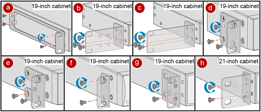
- Use M4 screws to attach a front mounting bracket delivered with the switch to each side of the switch. Figure 1 shows the front mounting brackets delivered with different switch models and associated installation methods.
- To install a 250 mm x 180 mm (9.8 in. x 7.1 in. W x D) switch in a 19-inch cabinet, use the front mounting brackets shown in c of Figure 1 (purchased separately, part number of 21240477).
- To install a 220 mm (8.7 in.) deep switch in a 21-inch cabinet, install the front mounting brackets according to h of Figure 1.
- See Figure 1 for the number of screws required for each mounting bracket.
- Connect the ground cable to the switch. For details, see step 2 and step 3 in Connecting the Ground Cable.
This step is optional. For switch models with the ground point at the left or right side of the chassis, connect the ground cable before mounting the switch in the cabinet or rack.
- Install floating nuts on the mounting rails of the cabinet.
Determine the installation position of the switch and use a flat-head screwdriver to install two floating nuts on each front mounting rail accordingly. Leave a gap of one mounting hole between the two floating nuts and ensure that they are level with those on the other rail.
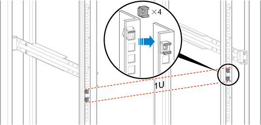
Pay attention to the scale markings on the mounting rails because three adjacent mounting holes may not be 1 U.
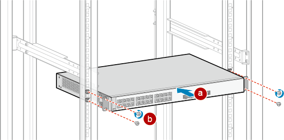
- Install the switch in the cabinet. The methods for installing switches that use different front mounting brackets are the same. Figure 2 shows an example.
- Hold the bottom of the switch and align the holes on the front mounting brackets with the floating nuts on the front mounting rails.
- Secure the mounting brackets to the mounting rails with M6 screws (two on each side) using a Phillips screwdriver.