Connecting the RPS1800 to a Switch
Context
The RPS1800 can connect to a maximum of six switches and ensure seamless failover for one switch if the internal power module of the switch fails. Among the six DC output ports, port 1 has the highest priority. The switch connected to port 1 preferentially receives power from the RPS1800.
If the RPS1800 uses the same external power supply system as the connected switches, it can prevent service interruption caused by failures of the switches' internal power modules. However, for improved reliability, if the RPS1800 uses a different external power supply system than the connected switches, it can prevent service interruption caused by failure of internal power modules and external power supply systems of the switches.


- Power cables of the RPS1800 must be routed indoors or buried underground if they are led in from the outside. Do not aerially route the power cables outdoors.
- Do not power on the switch until you finish installing the switch and connecting all cables.
- Power cables delivered with a switch are for use with this switch only.
Procedure
- Wear an ESD wrist strap or ESD gloves. When wearing an ESD wrist strap, ensure that it is in close contact with your wrist and grounded properly.
- Connect an RPS cable to the RPS1800.
- Insert one end of the RPS cable into an output port on the RPS1800 according to the networking plan. Ensure that the top side of the plug (marked "TOP") faces up.
- Tighten the captive screws on the plug.
Figure 1 Connecting an RPS cable to the RPS1800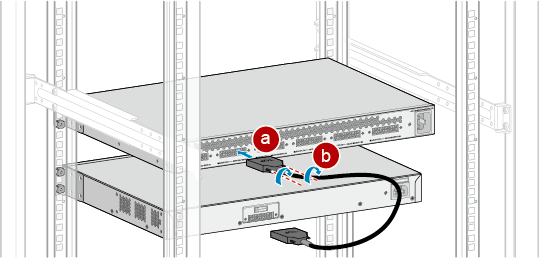
- Connect the RPS cable to a switch.
- Insert the other end of the RPS cable to the RPS input port at the rear of the switch. Ensure that the top side of the plug (marked "TOP") faces up.
- Tighten the captive screws on the plug.
Figure 2 Connecting the RPS cable to a switch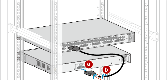
- Connect the RPS1800 power cable to the RPS1800.
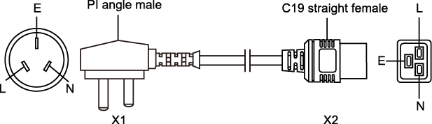
The RPS1800 uses a C19 straight female to PI angle male AC power cable, as shown in Figure 3. An RPS1800 power cable is connected in the same way as the AC power cable of a switch. For details, see Connecting Power Cables.
- Connect the RPS1800 power cable to an external power supply system.
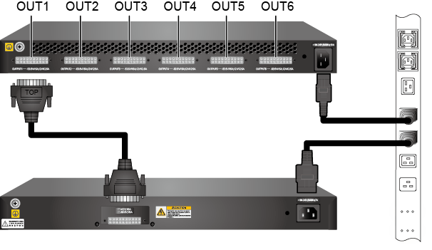
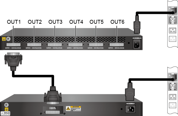
The power cables of the RPS1800 and switch can be connected to the same or different external power supply systems, as shown in Figure 4 and Figure 5, according to power reliability requirements.